Double power supply switching mechanism and automatic change-over switch

A technology of automatic transfer switch and dual power supply switching, which is applied in the direction of electric switches, circuits, electrical components, etc., and can solve the problems that the circuit breaker cannot realize the load buckle, the handle of the circuit breaker is broken, etc.

Active Publication Date: 2016-06-22
DELIXI ELECTRIC
View PDF3 Cites 2 Cited by
  • Summary
  • Abstract
  • Description
  • Claims
  • Application Information

AI Technical Summary

Problems solved by technology

[0007] Therefore, the purpose of the present invention is to provide a dual power supply switching mechanism to more effectively and time-savingly overcome the failure of the circuit breaker to realize the tripping due to insufficient tripping of the tripping of the circuit breaker, or the excessive travel of the tripping of the circuit breaker will cause the handle of the circuit breaker to A defect that breaks due to excessive load

Method used


Image

  • Double power supply switching mechanism and automatic change-over switch
  • Double power supply switching mechanism and automatic change-over switch
  • Double power supply switching mechanism and automatic change-over switch

Examples


Embodiment 1

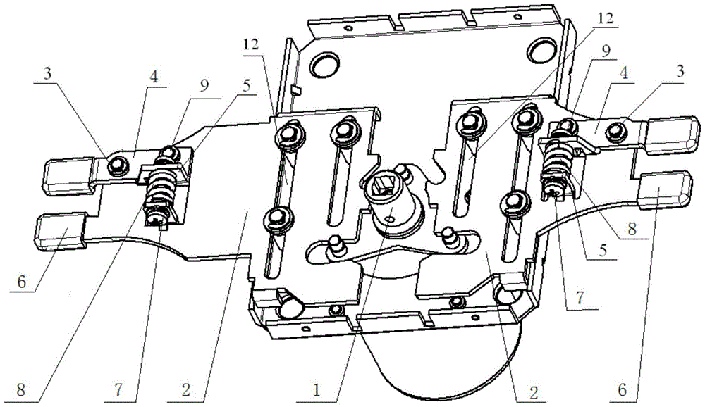
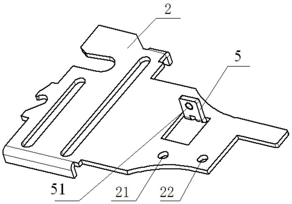
[0033] This embodiment provides a dual power switching mechanism, such as Figure 1 to Figure 6 As shown, it includes a turntable 1 and push pendulums 2 symmetrically arranged on both sides of the turntable 1, the turntable 1 drives the push pendulum 2 to swing, and also includes:

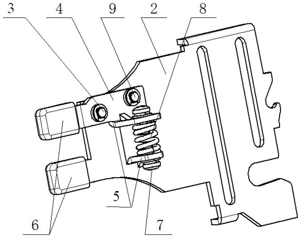
[0034] The adjusting pendulum 4 is rotatably fixed on the side of the push pendulum 2 away from the turntable 1;

[0035] The elastic member 8 is connected and arranged between the end of the adjustment pendulum 4 close to the turntable 1 and the push pendulum 2 .

[0036] During the loading and opening process of the circuit breaker of the dual power automatic transfer switch, the reaction force of the circuit breaker handle is applied to the adjustment pendulum, while the elastic member exerts force on the adjustment pendulum, and ensures that the adjustment pendulum and the circuit breaker handle are always in contact. On the premise that the load trip of the circuit breaker handle is sufficien...

Embodiment 2

[0051] This embodiment also provides an automatic transfer switch, including a circuit breaker and a dual power switching structure, characterized in that the dual power switching structure is the dual power switching structure provided by the present invention, and the swing adjustment in the dual power switching structure 4. The end away from the turntable 1 is connected to the handle of the circuit breaker.

[0052] The automatic transfer switch provided in this embodiment includes the dual power supply switching structure provided by the present invention, so it has the advantages of the dual power supply switching structure provided by the present invention. That is to say, in the automatic transfer switch provided in this embodiment, the dual power supply switching mechanism can use the elastic body to automatically adjust the adjusting pendulum according to the actual stroke of the circuit breaker handle in the process of loading the buckle, so that the circuit breaker h...


PUM


Abstract

The invention provides a double power supply switching mechanism and an automatic change-over switch. The double power supply switching mechanism includes a rotating disc and pushing pendulums symmetrically arranged at two sides of the rotating disc, the rotating disc drives the push pendulums to swing, and the double power supply switching mechanism also includes an adjusting pendulum rotatably fixed on one side of the rotating disc away from the pushing pendulums, and elastic pieces connected and arranged between one ends of the adjusting pendulums close to the rotating disc and the pushing pendulums. The abovementioned double power supply switching mechanism can utilize the elastic pieces to automatically adjust the adjusting pendulums according to the actual stroke of a breaker handle in a load buckling process, so that the breaker handle can be reset through load buckling, and does not break due to a too large load, and compared with using screws to adjust stroke allowances of pushing pendulums in the prior art, time is saved.

Description

technical field [0001] The invention relates to the technical field of automatic transfer, in particular to a dual power supply switching mechanism and an automatic transfer switch. Background technique [0002] The dual power supply automatic transfer switch is a switching device that automatically switches the load circuit from one power supply to another (standby) power supply. It is mainly used in emergency power supply systems. When there is a problem with the common power supply and cannot continue to supply power to the load equipment, it is switched to the backup power supply, so as to ensure the normal and continuous operation of the load equipment. [0003] A dual power automatic transfer switch usually includes two circuit breakers and a switching mechanism arranged between the two circuit breakers. The switching structure generally includes a turntable and a push pendulum symmetrically arranged on both sides of the turntable, and the turntable is used to drive t...

Claims


Application Information

Patent Timeline
Patent Type & Authority Applications(China)
IPC IPC(8): H01H9/26
CPCH01H9/26
Inventor 袁亦峰宋志文
Owner DELIXI ELECTRIC
Why Eureka
Try Eureka