COB welding method and manufacturing method

A manufacturing method and wire bonding technology, which is applied in semiconductor/solid-state device manufacturing, semiconductor devices, electrical components, etc., can solve the problems of prolonging COB manufacturing time and welding wire confusion, so as to reduce the frequency of replacing the welding wire process and reduce confusion probability, the effect of improving welding efficiency

Active Publication Date: 2016-06-22
HONGLI ZHIHUI GRP CO LTD
View PDF4 Cites 2 Cited by
  • Summary
  • Abstract
  • Description
  • Claims
  • Application Information

AI Technical Summary

Problems solved by technology

The delay time for each replacement of the welding wire process will prolong the COB manufacturing time; in addition, frequent switching between different welding wires will easily cause welding wire confusion

Method used


Image

  • COB welding method and manufacturing method
  • COB welding method and manufacturing method

Examples


Embodiment Construction

[0030] The present invention will be further described below in conjunction with the accompanying drawings of the description.

[0031] A COB manufacturing method, comprising a solid crystal step and a wire bonding step, comprising the following steps:

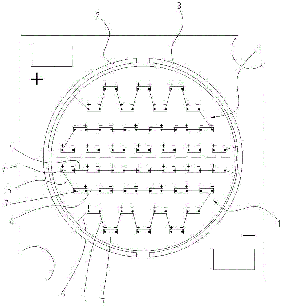
[0032] (1) solid crystal; such as figure 1 As shown, a circular crystal-bonding area is provided in the middle of the substrate, and positive electrode pads 2 and negative electrode pads 3 are respectively provided on both sides of the crystal-bonding area; the positive electrode pads and negative electrode pads are arc-shaped, And it is arranged along the edge of the crystal-bonding area; several LED chips 7 are respectively fixed in the two symmetrical half regions of the crystal-bonding area to form two light-emitting units 1, and the LED chips 7 of the two light-emitting units 1 are arranged symmetrically; the light-emitting In unit 1, the LED chips 7 arranged in a line are close to the middle of the die-bonding area, and...


PUM


Abstract

The invention provides a COB manufacturing method. The COB manufacturing method comprises a substrate manufacturing step, a die bonding step and a wire bonding step, wherein the wire bonding step comprises the following steps: step (1), in a plurality of LED (Light-Emitting Diode) chips which are arranged in an in-line arrangement, connecting adjacent LED chips by first line arc bonding wires to form first series branches; step (2), connecting adjacent first series branches end to end by a second line arc bonding wire to form a second series branch; step (3), in two rows of staggered LED chips, connecting adjacent LED chips by the second line arc bonding wire to form a third series branch; step (4), connecting the second series branches and the third series branch end to end by the second line arc bonding wire to form a fourth series branch; and step (5), connecting positive and negative electrodes and a bonding pad of the fourth series branch by a third line arc bonding wire. Since three line arc bonding wires are welded separately and independently, thus the frequency of replacing a bonding wire process by a wire bonding machine can be reduced, the welding efficiency can be improved and the probability of occurrence of confusions can be reduced.

Description

technical field [0001] The invention relates to COB technology, in particular to a COB welding method and manufacturing method. Background technique [0002] The COB manufacturing process generally includes several steps of solid crystal and wire bonding. The traditional COB wire bonding method is soldered according to the arrangement order of the LED chips. Due to the different arrangement positions and spacing distances of the LED chips, LED chips may need to Different wire bonding processes, in this way, if all LED chips of COB are bonded according to the traditional wire bonding method, the wire bonding machine needs to switch multiple wire bonding processes to complete the wire bonding step. The delay time for each replacement of the welding wire process will prolong the COB manufacturing time; in addition, frequent switching between different welding wires will easily cause welding wire confusion. Contents of the invention [0003] The technical problem to be solved...

Claims


Application Information

Patent Timeline
Patent Type & Authority Applications(China)
IPC IPC(8): H01L21/60H01L33/00H01L33/62
CPCH01L24/85H01L33/005H01L33/62H01L2224/85986H01L2933/0066H01L2224/48137
Inventor 周志勇陈晓彬马思达翁平
Owner HONGLI ZHIHUI GRP CO LTD
Why Eureka
Try Eureka