Supercharge Your Innovation With Domain-Expert AI Agents!

Electronic equipment, method for preparing electronic equipment casing, and stamping die

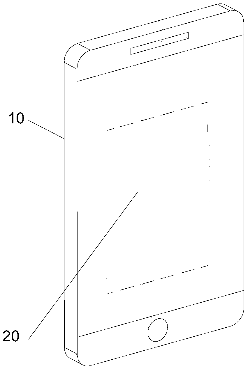
A technology for electronic equipment and stamping dies, which is applied in the field of workpiece stamping and can solve problems such as complex assembly processes

Active Publication Date: 2018-08-31
LENOVO (BEIJING) LTD
View PDF6 Cites 0 Cited by
  • Summary
  • Abstract
  • Description
  • Claims
  • Application Information

AI Technical Summary

Problems solved by technology

[0005] Since the metal shell is assembled and welded by the upper metal shell and the lower metal shell, the assembly process is more complicated

Method used


Image

  • Electronic equipment, method for preparing electronic equipment casing, and stamping die
  • Electronic equipment, method for preparing electronic equipment casing, and stamping die
  • Electronic equipment, method for preparing electronic equipment casing, and stamping die

Examples


Embodiment approach 1

[0127] Such as Figure 4 As shown, the pre-processed part A10 includes a first side wall A1 extending from the outer edge of the bottom case 11 to the first direction, and the first side wall A1 includes: The first part A11 and the second part A12 connected in sequence in one direction.

[0128] Step 1: Manufacture a first semi-finished product B10 by processing the first side wall A1 of the pre-processed part A10, so that the second part A12 of the first semi-finished product B10 and the first part A11 form a second a predetermined angle.

[0129] The second step: by processing the second part A12 of the first side wall of the first semi-finished product B10, a second semi-finished product C10 is produced, and the first part 121 of the eaves is formed on the second semi-finished product C10, The outer surface of the first part 121 of the eaves intersects the outer surface of the first part A11 of the first side wall to form an intersection line 14, and the outer surface of ...

Embodiment approach 2

[0139] Such as Figure 5 As shown, the pre-processed part A10 includes a first side wall A1 extending from the outer edge of the bottom case 11 to the first direction, and the first side wall A1 includes: The first part A11 and the second part A12 connected in sequence in one direction.

[0140] Step 1: Manufacturing a third semi-finished product D10 by machining the second portion A12 of the first side wall A1 of the prefabricated part A10 such that the first portion of the eaves of the third semi-finished product D10 The outer surface of the eaves 121 intersects the outer surface of the first part A11 of the first side wall to form an intersection line 14, and the outer surface of the first part 121 of the eaves and the first part A11 of the first side wall The outer surface is at right angles.

[0141] The second step: by processing the remaining part 122 of the second part of the first side wall of the third semi-finished product D10 except the first part of the eaves 12...


PUM


Abstract

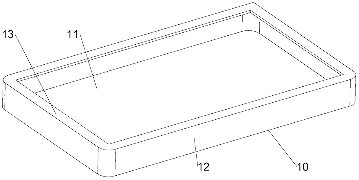
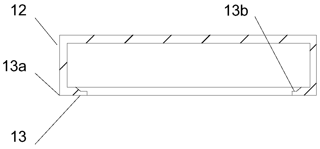
The invention relates to an electronic device, a preparation method of an electronic device shell and a stamping mould and belongs to the electronic device field. The main objective of the invention is to simplify the assembly process of electronic device metal shells. The preparation method of the electronic device shell is used for stamping a preprocessed component made of a metal material; the preprocessed component comprises a bottom shell and a first side wall which extends from the outer edge of the bottom shell to a first direction; the first side wall includes a first portion and a second portion which are connected sequentially from the bottom shell along the first direction; and the bottom shell and the first side wall form a containing space. The method includes the following steps that: the preprocessed component is arranged in the mould; and the second portion of the first side wall is squeezed through a preset squeezing mode, so that the second portion can form the top eave of the shell, and the first portion of the first side wall forms the side wall of the shell, and the top eave extends from the top end of the side wall towards the second direction of the center of an end surface formed by the top end of the side wall, and therefore, the electronic device shell can be fabricated. The bottom shell, the side wall and the top eave are the shell formed by integral molding of one metal plate.

Description

technical field [0001] The invention relates to the technical field of workpiece stamping, in particular to an electronic device, a method for preparing a housing of the electronic device, and a stamping die. Background technique [0002] The use of a metal shell on the mobile phone will bring a strong texture to the mobile phone itself, which is favored by the majority of users. [0003] During the manufacturing process of the metal shell, the metal shell is assembled and spliced ​​by an upper metal shell and a lower metal shell. The lower metal shell includes a bottom shell and side walls extending upward from the bottom shell. The upper metal shell is a metal plate with a hole in the middle for placing the screen. The metal plate is assembled and welded on the side wall of the lower metal shell , constitute the eaves of the metal shell, that is, the manufacture of the metal shell is completed. [0004] In the course of realizing the present invention, the inventor finds...

Claims


Application Information

Patent Timeline
Patent Type & Authority Patents(China)
IPC IPC(8): H05K5/04B21D37/10
Inventor 张成浩栾北欧
Owner LENOVO (BEIJING) LTD
Features
  • R&D
  • Intellectual Property
  • Life Sciences
  • Materials
  • Tech Scout
  • Unparalleled Data Quality
  • Higher Quality Content
  • 60% Fewer Hallucinations
Learn More