Cutting device for sectional materials

A technology for cutting devices and profiles, applied in the direction of shearing devices, shearing machine accessories, shearing machine equipment, etc., can solve the problems of low profile cutting efficiency and poor profile cutting quality, and achieve easy operation and improved safety , the effect of improving the accuracy

Inactive Publication Date: 2016-06-29
柴德维
View PDF9 Cites 2 Cited by
  • Summary
  • Abstract
  • Description
  • Claims
  • Application Information

AI Technical Summary

Problems solved by technology

[0003] The object of the present invention is to provide a high-strength, Easy to operate, good stability of profile during cutting, high working quality and good cutting quality Cutting device for profile

Method used


Image

  • Cutting device for sectional materials
  • Cutting device for sectional materials

Examples


Embodiment Construction

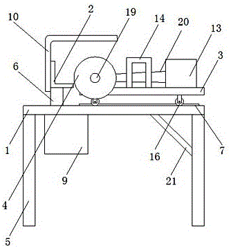
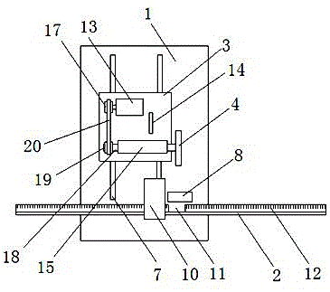
[0014] as attached figure 1 and 2 Shown: a cutting device for profiles, including an operating table 1, a backing plate 2, a moving plate 3 and a cutting wheel 4, characterized in that: the operating table 1 is set on a bracket 5, and on the operating table 1 A fixed block 6, a guide rail 7, a chip discharge port 8, and a chip collection box 9 are arranged on the top, and a reinforcing rod 21 is arranged between the console 1 and the bracket 5, and the gap between the console 1 and the bracket 5 is improved by the reinforcing rod 21. The strength of the connection between them improves the strength of the cutting device. The chip outlet 8 and the chip box 9 on the console 1 can collect the chips in a concentrated manner, which improves the environmental protection performance. The backing plate 2 is arranged on the fixed block 6, and a protective cover 10, a cutout 11, and a scale 12 are arranged on the backing plate 2. The backing plate 2 is set in an L-shaped structure, and...


PUM


Abstract

The invention discloses a cutting device for profiles, which includes an operating table, a backing plate, a moving plate and a cutting wheel, and is characterized in that: the operating table is set on a support, and a fixed block, guide rail, chip discharge port, and chip collection box. The backing plate is arranged on the fixed block, and a protective cover, a cutting port, and a scale are arranged on the backing plate. A motor, a handle, a positioning blocks, rollers, and the rollers are arranged on the guide rail, the fixed block is provided with a rotating shaft, and one end of the rotating shaft is provided with a driven wheel, and the cutting wheel is arranged on the rotating shaft. In the present invention, a scale, a cutout, and a protective cover are provided on the spacer, and the length of the profile that needs to be cut can be measured through the scale and the cutout, so as to improve the accuracy of the length of the profile, and the protective cover can not only avoid the cutting process of the profile The flying of debris generated in the process can also improve the safety of the profile during the cutting process.

Description

technical field [0001] The invention relates to a cutting device, in particular to a cutting device for profiles. Background technique [0002] During the processing of building profiles, it is necessary to cut the profiles into sections of different lengths and lengths according to the actual situation. The original cutting method is to mark on the profile according to the actual required length, and cut at the mark. This method has labor intensity. Large, low work efficiency, and large cutting errors. For example, the patent application number 201520426851.2 discloses an aluminum profile cutting device, which solves the problem that the waste generated during the profile cutting process is inconvenient to discharge and lacks a device for collecting waste. However, it has the disadvantages that the profile cutting efficiency is not high and the profile cutting quality is not good due to the low firmness of the profile during the cutting process. Contents of the invention ...

Claims


Application Information

Patent Timeline
Patent Type & Authority Applications(China)
IPC IPC(8): B23D19/00B23D33/00B23D33/12
CPCB23D19/00B23D33/00B23D33/12
Inventor 柴德维
Owner 柴德维
Why Eureka
Try Eureka