
Pumpback type friction stir welding head based on parallel mechanism

A friction stir welding and friction stir technology, which is used in welding equipment, non-electric welding equipment, metal processing equipment, etc., can solve the problems of complex product structure and welding seam form, slow response speed of series mechanism, and large error transmission. High torque and high bearing capacity, easy kinematic decoupling calculation, and the effect of ensuring surface integrity

Inactive Publication Date: 2016-06-29
SHANGHAI AEROSPACE EQUIP MFG GENERAL FACTORY
View PDF7 Cites 4 Cited by
  • Summary
  • Abstract
  • Description
  • Claims
  • Application Information

AI Technical Summary

Problems solved by technology

[0003] However, there are two problems to be solved in the current conventional friction stir welding technology and equipment:
[0004] (1) There is a keyhole at the end of the friction stir welding seam, which is caused by the fact that the stirring head is pulled out after the welding technology and the material cannot be replenished, which will affect the welding quality and the reliability of the structure
At present, the lead-in and lead-out plates are usually used to pull the keyhole to the lead-out plate, and then take it out by mechanical means. This method will cause waste of materials and will also affect welding efficiency.
[0005] (2) At present, the friction stir welding equipment generally adopts the series mechanism, but the series mechanism has the disadvantages of slow response speed, poor rigidity, and large error transmission.
However, in products such as automotive aluminum alloy wheels and electronic cold plates, the requirements for product safety, aesthetics, and production efficiency are relatively high, and the product structure and weld form are complex, especially the response of the welding of curved welds to equipment. The speed requirement is high, and the tandem equipment is difficult to meet the welding requirements

Method used


Image

  • Pumpback type friction stir welding head based on parallel mechanism
  • Pumpback type friction stir welding head based on parallel mechanism

Examples


Embodiment Construction

[0020] The invention will be described in more detail hereinafter with reference to the accompanying drawings showing embodiments of the invention. However, this invention may be embodied in many different forms and should not be construed as limited to the embodiments set forth herein.

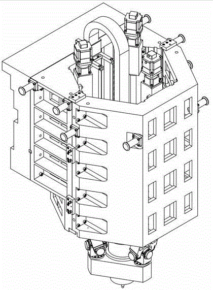
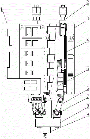
[0021] Such as figure 1 As shown, the retractable friction stir welding head based on the parallel mechanism provided by the preferred embodiment of the present invention includes: the rear mounting seat 1 of the friction stir welding head, the drive assembly 2 of the PRS mechanism, the front mounting plate 3 of the friction stir welding head, and the ball Lead screw subassembly 4, linear moving plate 5, hinge plate 6, Hooke hinge assembly 7, parallel head-spindle installation moving platform 8, retractable electric spindle 9.

[0022] The rear mounting base 1 of the friction stir welding machine head is installed with the Z-axis sliding plate through screws, so as to realize the connection ...


PUM


Abstract

The invention discloses a pumpback type friction stir welding head based on a parallel mechanism. A rear mounting base of the friction stir welding head and a Z-axis slide carriage are mounted through screws, so that connection of the head and a lathe body is achieved. Each PRS mechanism assembly is composed of a linear mobile plate, a hinge plate and a hooke joint assembly, wherein the linear mobile plate is connected with a ball screw pair assembly, and the hinge plate is connected with the linear mobile plate and the hooke joint assembly through hinge shafts. The PRS mechanism assemblies drive the ball screw pair assembly to rotate through a PRS mechanism drive assembly, then the linear mobile plates are made to move up and down, the hinge plates are driven to move by the hinge shafts, and the motion is transmitted to the hooke joint assemblies and then to a parallel head-spindle mounting mobile platform which is connected with the hooke joint assemblies; and as a pumpback type electric spindle is connected with the parallel head-spindle mounting mobile platform, the location of the pumpback type electric spindle also changes while the mobile platform moves.

Description

technical field [0001] The invention relates to the field of friction stir welding, in particular to a retractable friction stir welding head based on a parallel mechanism. Background technique [0002] With the rapid advancement of modern industrialization, functional integration, lightweight, low energy consumption, informatization of manufacturing process and green environmental protection have become the most prominent R&D concepts of industrial products, especially in the field of rail transit, automobile manufacturing, shipbuilding, etc. Traditional light metal alloy connection technologies such as fusion welding, riveting, and screwing in the fields of industry and energy can no longer meet the requirements of products in terms of reliability, efficiency, cost, energy consumption, and connection quality. Friction Stir Welding (Friction Stir Welding, FSW) is a solid-phase plastic connection with outstanding process characteristics such as low stress, small deformatio...

Claims


Application Information

Patent Timeline
Patent Type & Authority Applications(China)
IPC IPC(8): B23K20/12
Inventor 周法权林永勇徐晓霞张华德宫秀梅郭立杰
Owner SHANGHAI AEROSPACE EQUIP MFG GENERAL FACTORY
Learn More