Multi-station rotational forming machine

A molding machine and multi-station technology, which is applied in the field of injection blowing or injection stretch blowing plastic bottle manufacturing equipment, can solve the problems of limited output of molding machines, expansion of floor space, and increase of equipment volume, so as to shorten the processing cycle and increase the output. , the effect of reducing the rotation angle

Active Publication Date: 2016-06-29
柳州市精业机器有限公司
View PDF6 Cites 16 Cited by
  • Summary
  • Abstract
  • Description
  • Claims
  • Application Information

AI Technical Summary

Problems solved by technology

[0003] However, the output of the above-mentioned molding machines is limited. When it is necessary to increase the output, it can only be solved by adopting a double-row or multi-row mold arrangement on the basis of the original structure.
And every time a row of molds is added, the diameter of the rotating disk used to drive the injection mold and blow molding module in the equipment will increase correspondingly, resulting in an increase in the volume of the equipment and the expansion of the occupied area.

Method used


Image

  • Multi-station rotational forming machine
  • Multi-station rotational forming machine
  • Multi-station rotational forming machine

Examples


Embodiment 1

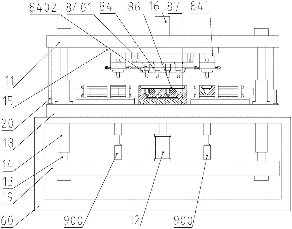
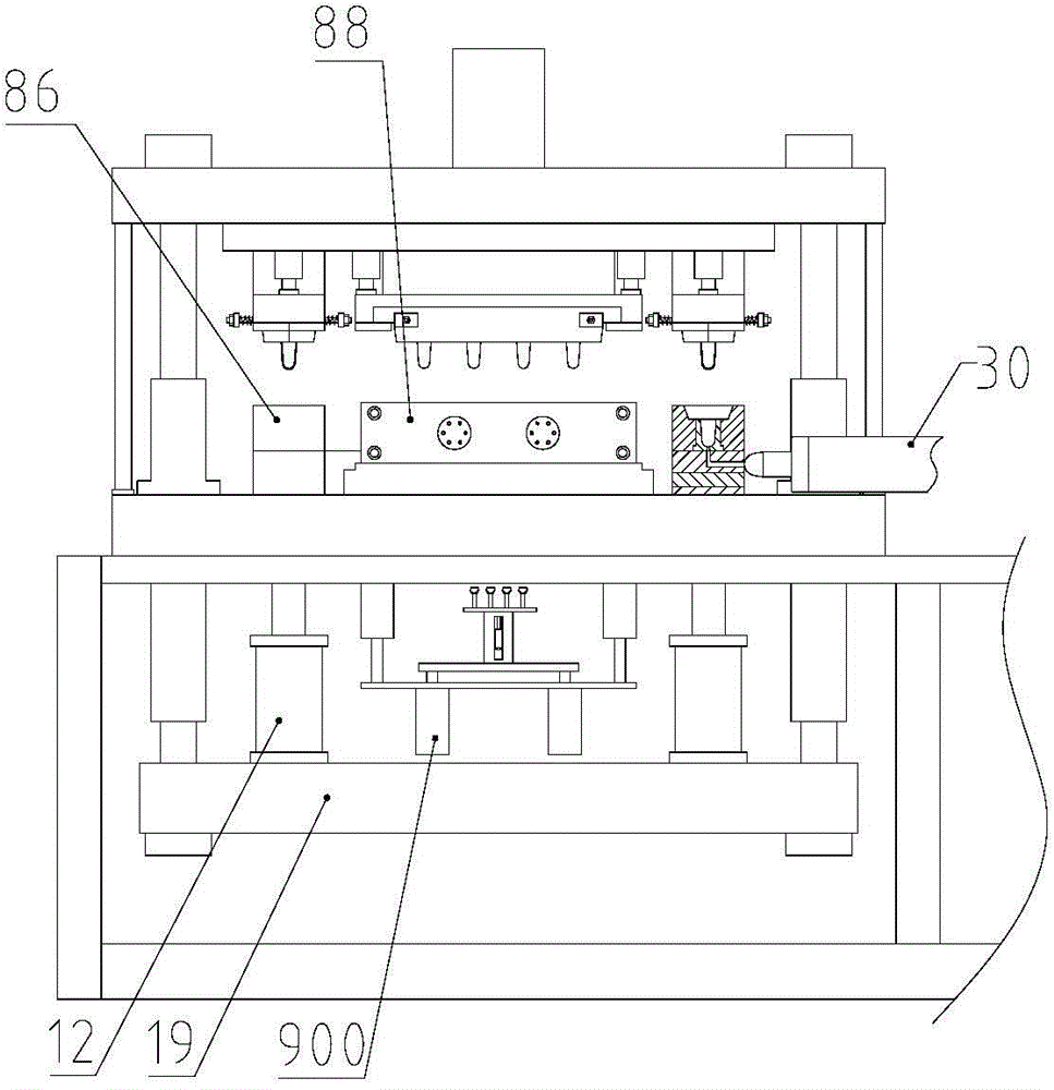
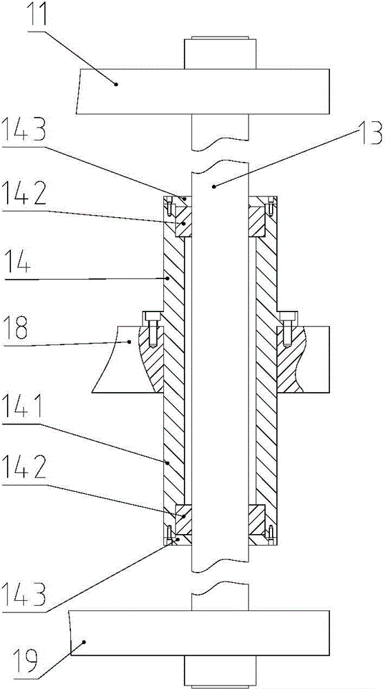
[0036] figure 1 It is a schematic diagram of the overall structure of the present invention; figure 2 for figure 1 side view. Such as figure 1 and combine figure 2 As shown, the present invention provides a multi-station rotary molding machine. In this embodiment, the injection blowing equipment is taken as an example to describe the technical solution in detail. Specifically, the multi-station rotary molding machine includes a main machine and an injection mold set and a blow molding set arranged on the main machine; the main machine includes a frame 60 and a workbench panel 18 arranged above the frame 60, and The workbench panel 18 is horizontally fixed on the frame 60 , the workbench panel 18 is connected with the lower formwork 19 through the clamping oil cylinder 12 , and the lower formwork 19 is connected with the upper formwork 11 through the guide column 13 passing through the workbench 18 vertically. More specifically, the bottom surface of the workbench panel ...

Embodiment 2

[0050] Figure 16 It is a schematic diagram of the structure of the double-row mold in the second embodiment of the present invention. In the first embodiment above, the molds arranged on the injection mold set and the blow molding set are arranged in a single row. For products with greater output requirements, such as Figure 16 As shown, double or multi-row arrangements are also possible. The difference between this embodiment and the first embodiment lies in the arrangement of the molds on the injection mold and the blowing mold. Other technical features are the same as those of the first embodiment. For details, please refer to the first embodiment, which will not be repeated here.

Embodiment 3

[0052] Figure 17 A schematic diagram of the overall structure of Embodiment 3 of the present invention. Such as Figure 17 As shown, in addition to the structures of the above two embodiments, in fact, on the premise that the space for the rotating disk 15 is allowed, in order to further increase the output, the number of injection molds and blow molds can be set more, Those skilled in the art can make reasonable structural settings according to actual needs. In this embodiment, the number of the injection mold group and the blow mold group is three groups, such as Figure 17 Shown in is the setting position structure of the concave mold group 86 and the blow mold group 88 on the workbench panel 18, as Figure 17 It can be seen that the setting interval angle between two adjacent modules is 60°. control figure 1 As shown, six sets of die sets 84 can be correspondingly arranged on the rotating disk 15, and the interval angle between two adjacent die sets 84 is 60°.

[00...


PUM


Abstract

The invention discloses a multi-station rotational forming machine. The multi-station rotational forming machine comprises a host machine, injection mould sets, and blowing mould sets; the host machine comprises a rotary driving mechanism (16), and a rotary disk (15) connected with the rotary driving mechanism, and also comprises a workbench panel (18) below the rotary disk; the injection mould sets and the blowing mould sets are arranged on the rotary disk and the workbench panel at equal interval angles. According to the multi-station rotational forming machine, preferable utilization of the space of the rotary disk is realized, yield is increased, and at the same time equipment equilibrium stability is improved; and in addition, the rotating angle is smaller than that in the prior art, so that processing period is shortened, and production efficiency is increased further.

Description

technical field [0001] The invention relates to an injection-blow or injection-stretch-blow plastic bottle manufacturing equipment, in particular to a multi-station rotary molding machine. Background technique [0002] Blow molding is the third largest plastic molding method after injection molding and extrusion molding, and it is also the fastest growing plastic molding method. The invention patent with the patent number ZL200920303237.1 discloses a dual-station reciprocating rotary injection-blow molding machine, including two sets of identical core modules I and II corresponding to a set of injection molds and The blow molding module realizes the alternate operation of injection molding and blow molding, and then completes the entire processing process of the product. The relevant content of this patent is used in combination in the present invention. [0003] But its output of above-mentioned forming machine is limited, when needing to increase output, can only solve b...

Claims


Application Information

Patent Timeline
Patent Type & Authority Applications(China)
IPC IPC(8): B29C49/06B29C45/26B29C49/48B29C45/40B29C49/38B29C49/70
Inventor 文澜李晖梁家炳肖彩飞姚林平
Owner 柳州市精业机器有限公司
Why Eureka
Try Eureka