
Method and Apparatus for Operating a Braking Device, Braking Device

A brake device and equipment technology, applied in the direction of brake transmission, brake parts, brakes, etc., can solve the problems of inaccurate brake disc-temperature-model, loss of clamping force, etc., to improve accuracy and reduce components load, reducing the effect of misestimating the effect of

Active Publication Date: 2016-06-29
ROBERT BOSCH GMBH
View PDF6 Cites 9 Cited by
  • Summary
  • Abstract
  • Description
  • Claims
  • Application Information

AI Technical Summary

Problems solved by technology

Today's brake devices have the disadvantage that a loss of clamping force can occur if the brake device cools down after the stopping moment
However, today's brake disc-temperature models are relatively imprecise, since they are additionally influenced by many environmental variables such as temperature, weather conditions, wheel material and shape, wheel guards, wheel size, add-ons and similar factors

Method used


Image

  • Method and Apparatus for Operating a Braking Device, Braking Device
  • Method and Apparatus for Operating a Braking Device, Braking Device
  • Method and Apparatus for Operating a Braking Device, Braking Device

Examples


Embodiment Construction

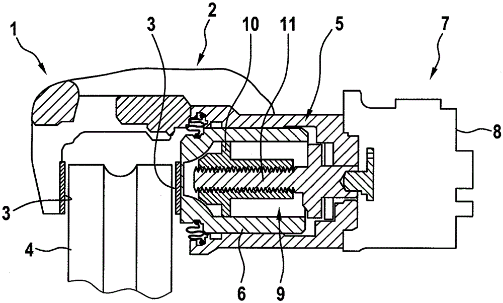
[0022] figure 1 A wheel brake device 1 of a motor vehicle, which is not shown in detail here, is shown in a simplified sectional illustration. The wheel brake device 1 is designed as a disc brake and for this purpose has a brake caliper 2 with brake linings 3 between which the brake pads 3 can be clamped or clamped with The wheels of the motor vehicle have brake discs 4 connected in a rotationally fixed manner. For this purpose, a hydraulic actuator 5 is assigned to the brake caliper 2 , which has a brake piston 6 which can be hydraulically actuated in order to move the The brake disc 4 is clamped between the brake linings 3 . During driving operation, a braking torque is thus applied to brake disk 4 and thus to the wheels, which serves to decelerate the vehicle.

[0023] In addition, the wheel brake device 1 is designed as a parking brake device and has an electric actuator 7 for this purpose, which is composed of an electric motor 8 , an actuator drive 9 designed here as ...


PUM


Abstract

A method is used for operating a braking device (1) of a vehicle, in particular a parking brake device. The braking device (1) comprises an electromotive actuator (7) that displaces an actuator element (10) either into a clamping position for subjecting a brake disk (4) to a clamping force or into a release position for releasing the brake disk (4). A brake disk temperature is determined in order to activate the actuator (7) depending on the determined brake disk temperature. The brake disk temperature is determined depending on at least one actuator current value.

Description

technical field [0001] The invention relates to a method for operating a brake device of a vehicle, in particular a parking brake device, wherein the brake device has an electric actuator which can selectively move an actuator element to In a clamping position (Zuspannstellung) in which a clamping force is applied to the brake disc or in a release position in which the brake disc is released, wherein the brake disc temperature is ascertained in order to control the brake disc as a function of the ascertained brake disc temperature Actuator. [0002] Furthermore, the invention relates to a device for carrying out the method as well as to a braking device having such a device. Background technique [0003] Methods, devices and braking devices of the type mentioned at the outset are known from the prior art. In particular, automatic parking brake systems of the "motor-on-caliper" type are usually used on the rear wheel brakes of motor vehicles in order to apply the wheels of ...

Claims


Application Information

Patent Timeline
Patent Type & Authority Applications(China)
IPC IPC(8): B60T13/74
CPCB60T13/74B60T13/745B60T13/741F16D55/226F16D65/183F16D2121/04F16D2121/24F16D2125/40B60T8/171B60T8/172
Inventor F.贝尔勒-米勒D.布拉泰特S.豪贝尔H.沃尔夫
Owner ROBERT BOSCH GMBH
Learn More