Air pressure feeding device

A feeding device and air pressure technology, applied in the field of air pressure feeding mechanism, can solve the problems of high manufacturing and maintenance costs, numerous parts, complex structure, etc., achieve the effects of simplified structure, simple and practical mechanism structure, and reduced production cost

Inactive Publication Date: 2016-06-29
YANTAI NANSHAN UNIV
View PDF6 Cites 16 Cited by
  • Summary
  • Abstract
  • Description
  • Claims
  • Application Information

AI Technical Summary

Problems solved by technology

However, most feeding equipment has a complex structure, a large numb

Method used


Image

  • Air pressure feeding device
  • Air pressure feeding device

Examples


Embodiment Construction

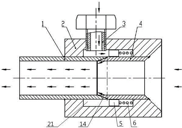
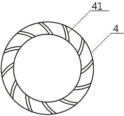
[0010] Such as figure 1 Shown is a pneumatic feeding device, comprising an inner cone sleeve 1 communicated with the material input end, an outer cone sleeve 4 communicated with the material output end, and the left end surface of the outer cone sleeve 4 has a section of outer truncated cone 12 corrugated protrusions 41 are provided on the conical surface, and the right end surface of the inner cone sleeve 1 has a section inner truncated conical surface, and its taper is the same as the angle of the truncated conical surface of the outer cone sleeve 4; The shape protrusion 41 makes the gap 14 formed between the inner cone sleeve 1 and the outer cone sleeve 4; the inner cone sleeve 1 and the outer cone sleeve 4 are sealed with an outer sleeve 2, and the outer sleeve 2 is in the corresponding A cavity 21 is set at the gap 14, and a pipe fitting 3 connecting the outlet end of the high-pressure air pump with the cavity 21 is also set on the outer sleeve 2; a piston 5 is also set i...


PUM


Abstract

The invention relates to an air pressure feeding device. The air pressure feeding device comprises an inner conical opening sleeve communicating with the material input end, and an outer conical opening sleeve communicating with the material output end. The left end face of the outer conical opening sleeve is provided with an outer segment butt circular conical face which is provide with a plurality of ridge-shaped protrusions. The right end face of the inner conical opening sleeve is provided with an inner segment butt circular conical face, and the taper of the inner segment butt circular conical face is equal to that of the butt circular conical face of the outer conical opening sleeve. Gaps are formed between the inner conical opening sleeve 1 and the outer conical opening sleeve through the ridge-shaped protrusions. An outer sleeve is arranged outside the inner conical opening sleeve and the outer conical opening sleeve in a sealed mode. A cavity is formed in the positions, corresponding to the gaps, of the outer sleeve. A pipe enabling the high-pressure air pump outlet end to communicate with the cavity is further arranged on the outer sleeve. A piston is further arranged in the cavity, the cavity is divided into a left closed part and a right closed part through the piston, and springs are arranged in the right part. Compared with the prior art, the air pressure feeding device is simple in structure and practical, the structure of feeding equipment is simplified, the production cost is reduced, and the power-saving amount can reach 60% or more.

Description

technical field [0001] The invention relates to a material conveying device, in particular to a pneumatic feeding mechanism. Background technique [0002] All kinds of feeding equipment currently used have achieved the purpose of feeding, replacing traditional manual feeding, improving work efficiency and reducing labor costs. However, most of the feeding equipment has a complex structure and a large number of parts, and the cost of manufacturing and maintenance is relatively high. In order to use a simpler mechanism to achieve the purpose of material transportation, a new mechanism design is now provided. Contents of the invention [0003] The purpose of the present invention is to realize the functions of cumbersome feeding equipment through a simple mechanism, and achieve the purpose of energy-saving and high-efficiency conveying materials such as pellets and powders. [0004] The object of the present invention is achieved through the following technical solutions: ...

Claims


Application Information

Patent Timeline
IPC IPC(8): B65G53/52
CPCB65G53/523B65G53/526
Inventor 王春华杨丽娟丁丽娟
Owner YANTAI NANSHAN UNIV
Why Eureka
Try Eureka