
A mechanical arm and an excavator including the same

A robotic arm and robotic arm technology, applied in mechanically driven excavators/dredgers, earthmoving machines/shovels, construction, etc. The bucket oil seal is easily damaged and other problems, so as to reduce the working intensity, improve the effective utilization rate and prolong the service life.

Inactive Publication Date: 2017-12-01
卢孔法
View PDF6 Cites 0 Cited by
  • Summary
  • Abstract
  • Description
  • Claims
  • Application Information

AI Technical Summary

Problems solved by technology

[0002] As we all know, when the excavator is digging, the bucket will easily bring sediment and other particles into the pin shaft of the bucket when the bucket is turned, and the butter in the bucket will be gradually squeezed out of the pin shaft, so that the pin shaft and the bushing, tooling Parts such as the word frame and bucket connecting rod rub against each other with particles, which intensifies the wear of other parts such as the pin shaft and shortens the service life; the wear of other parts such as the pin shaft leads to greater mechanical vibration and noise large, which has a serious impact on the operator's body; the operator needs to apply butter to the pin shaft many times to relieve the wear of other parts such as the pin shaft, which greatly increases the workload of the operator and causes a waste of resources
[0003] The bucket oil seal of the excavator is most likely to be damaged, because the working surface in the bucket oil seal is close, and the mud will splash on the first hydraulic lever of the bucket when the bucket is excavated. Due to the needs of the operation of the excavator, sometimes the first hydraulic lever of the bucket The end is not fully retracted into the oil cylinder oil seal. After the excavator works, the temperature will become high, and the mud will solidify soon. When the solidified mud is cleaned, the oil seal will easily be damaged, resulting in hydraulic oil leakage.

Method used


Image

  • A mechanical arm and an excavator including the same
  • A mechanical arm and an excavator including the same
  • A mechanical arm and an excavator including the same

Examples


Embodiment Construction

[0035] In order to make the purpose, technical solution and advantages of the present invention more clear, the following will give descriptions of specific embodiments in conjunction with the accompanying drawings of the present invention, but not as any limitation to the present invention.

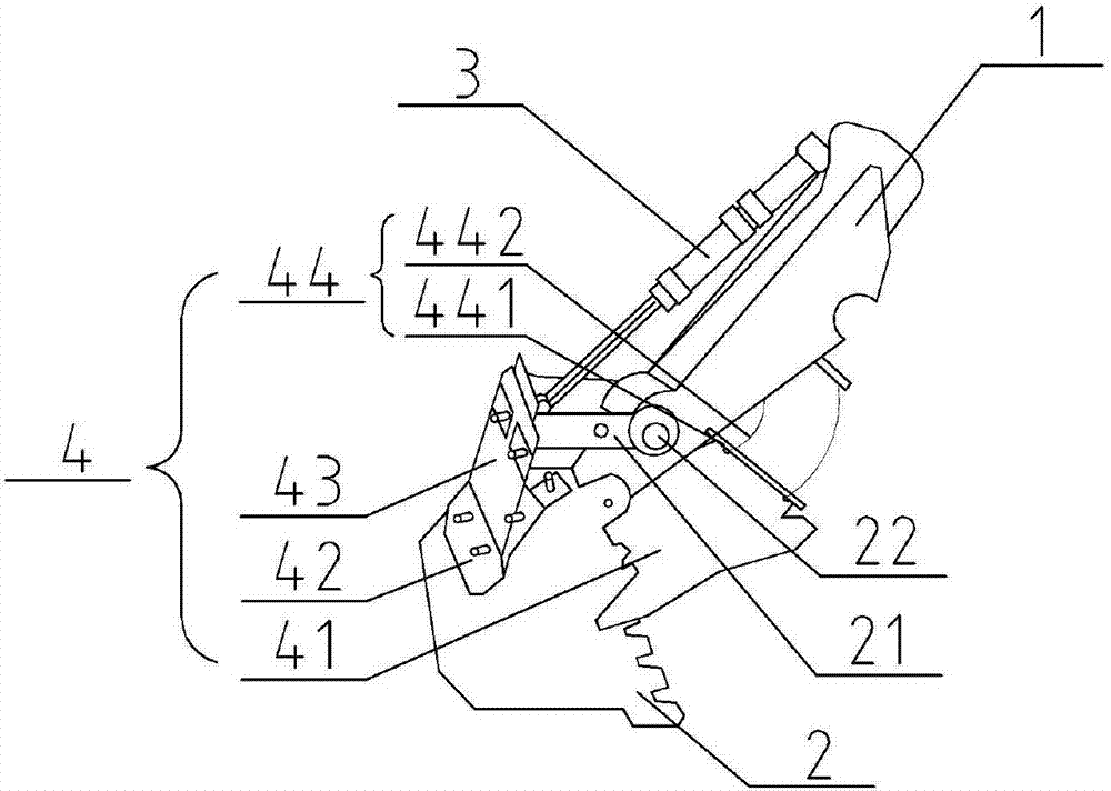
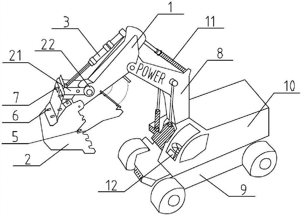
[0036] see Figure 1 ~ Figure 3 , a mechanical arm, including a mechanical arm 1, a bucket 2, a first hydraulic rod 3 and a protective device 4, one end of the mechanical arm 1 is connected to one end of the bucket 2, and the first hydraulic rod 3 One end is connected with one end of the bucket 2 , the other end of the first hydraulic rod 3 is connected with the other end of the mechanical arm 1 , and the protection device 4 is installed on the bucket 2 .

[0037] Further, the guard 4 includes a first guard 41, a second guard 42 and a third guard 43, one end of the first guard 41 is connected to the side wall of the bucket 2, and the other end of the first guard 41 passes through The co...


PUM


Abstract

The invention relates to a mechanical arm and an excavator with the same. The mechanical arm comprises a protective device, a bucket, a mechanical arm body and a first hydraulic rod. One end of the mechanical arm body is connected with one end of the bucket; one end of the first hydraulic rod is connected with one end of the bucket; the other end of the first hydraulic rod is connected with the other end of the mechanical arm body; and the protective device is installed on the bucket. The mechanical arm and the excavator with the same have the beneficial effects that the protective device is installed on the bucket, so that particulate matters are effectively blocked and prevented from entering a pin shaft, abrasion to other parts such as the bucket, an oil cylinder, the mechanical arm body and the pin shaft is reduced, and the service life is prolonged; noise generated during usage of the excavator is lowered; the working strength of operators is relieved; and the effective utilization ratio of resources is increased.

Description

technical field [0001] The present invention relates to the technical field of excavation, in particular to an excavator, in particular to a mechanical arm and an excavator including the mechanical arm. Background technique [0002] As we all know, when the excavator is digging, the bucket will easily bring sediment and other particles into the pin shaft of the bucket when the bucket is turned, and the butter in the bucket will be gradually squeezed out of the pin shaft, so that the pin shaft and the bushing, tooling Parts such as the word frame and bucket connecting rod rub against each other with particles, which intensifies the wear of other parts such as the pin shaft and shortens the service life; the wear of other parts such as the pin shaft leads to greater mechanical vibration and noise Large, it has a serious impact on the operator's body; the operator needs to apply butter to the pin shaft many times to alleviate the wear of other parts such as the pin shaft, which...

Claims


Application Information

Patent Timeline
Patent Type & Authority Patents(China)
IPC IPC(8): E02F3/28E02F3/36
CPCE02F3/283E02F3/36
Inventor 卢孔法
Owner 卢孔法
Learn More