
Reinforced-concrete draught fan tower

A technology for steel-concrete structures and wind turbine towers, which is applied in the installation/support of wind turbine configuration, wind power generation, sustainable manufacturing/processing, etc. problems, to achieve the effect of improving convenience, saving production time and reducing cost

Inactive Publication Date: 2016-06-29
DATANG HUBEI NEW ENERGY CO LTD
View PDF5 Cites 3 Cited by
  • Summary
  • Abstract
  • Description
  • Claims
  • Application Information

AI Technical Summary

Problems solved by technology

[0004] However, the height of the concrete tower itself is high, and the manufacturing process of the existing concrete tower is cumbersome and time-consuming, which greatly affects the production rate; at the same time, the torsional strength of the existing concrete tower itself is low, causing the fan tower to be easily damaged by the external wind. Shaking occurs under interference, which in turn causes the wind turbine to tilt, which affects the power generation of the wind turbine and the maintenance cost in the later period

Method used


Image

  • Reinforced-concrete draught fan tower
  • Reinforced-concrete draught fan tower
  • Reinforced-concrete draught fan tower

Examples


Embodiment 1

[0052] Such as Figure 5 and Figure 6 As shown, in this embodiment, the concrete tower 300 includes a top plate 39 set at the top and a support platform 200 set at the bottom. The top plate 39 is an annular support platform 200 set along the top of the side wall It is in the shape of a disk covering the bottom of the tower, the top plate 39 is coaxially arranged with the support platform 200, and the two ends of the multiple support steel bars 38 arranged at equal intervals are fixedly connected with the top plate 39 and the support platform 200 respectively to form a The supporting skeleton of the concrete tower 300 .

[0053] In this embodiment, the distances between the upper end of each supporting steel bar 38 and the center of the top plate 39 are equal, and the distance between the lower end and the center of the supporting platform 200 is equal, and the horizontal distance between the lower end of the supporting steel bar 38 and the axis of the tower is greater than t...

Embodiment 2

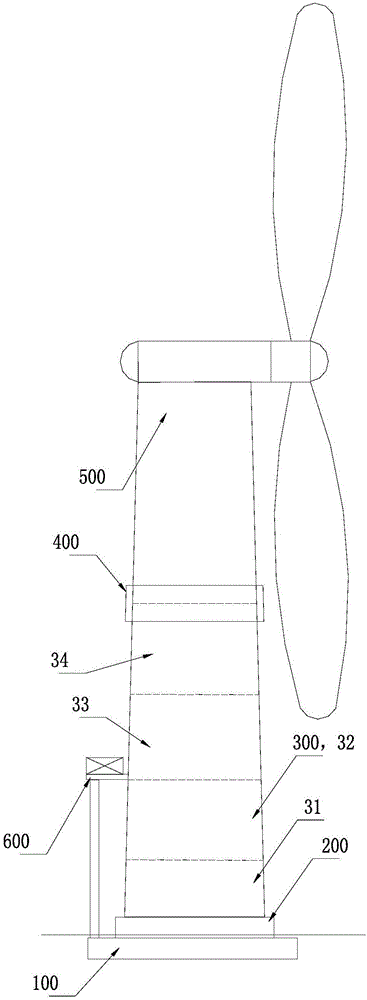
[0060] Such as figure 1 As shown, in this embodiment, the concrete tower 300 includes multiple sections of concrete towers poured sequentially from bottom to top, and each concrete tower section is a cylindrical structure arranged along the supporting frame to form the concrete tower 300 side wall of the tower. Preferably, the concrete tower tube 300 in this embodiment is divided into four sections for pouring in different batches, which are respectively from bottom to top, the first concrete tower section 31, the second concrete tower section 32, and the third concrete tower section The barrel section 33 and the fourth concrete tower section 34.

[0061] Such as Figure 6 to Figure 8 and Figure 12 As shown, in this embodiment, a plurality of prestressed steel bars 1 are arranged in the side wall of the concrete tower 300, and each prestressed steel bar 1 is arranged at equal intervals with respect to the axis of the tower; The grid-shaped steel bar group 21 forming the s...

Embodiment 3

[0070] Such as Figure 9 As shown, in this embodiment, the concrete tower 300 is formed by splicing a plurality of arc-shaped concrete tower sections 30; both sides of the concrete tower section 30 are respectively provided with Connected mother-in-law spelling strips. Therefore, the concrete tower 300 itself can be constructed by splicing and installing multi-segment concrete tower sections 30, so that the concrete tower 300 itself can realize the manufacturing process of pouring in batches and rapid assembly in the later stage, greatly speeding up the production of concrete The manufacturing speed of the tower tube 300 reduces the manufacturing difficulty.

[0071]In this embodiment, the left side of each concrete tower section 30 is respectively provided with a sub-strip, and the right side is respectively provided with a mother-strip, and the said mother-strip and the sub-strip are arranged in cooperation; the said sub-strip It is composed of protruding ribs 35 with a "T...


PUM


Abstract

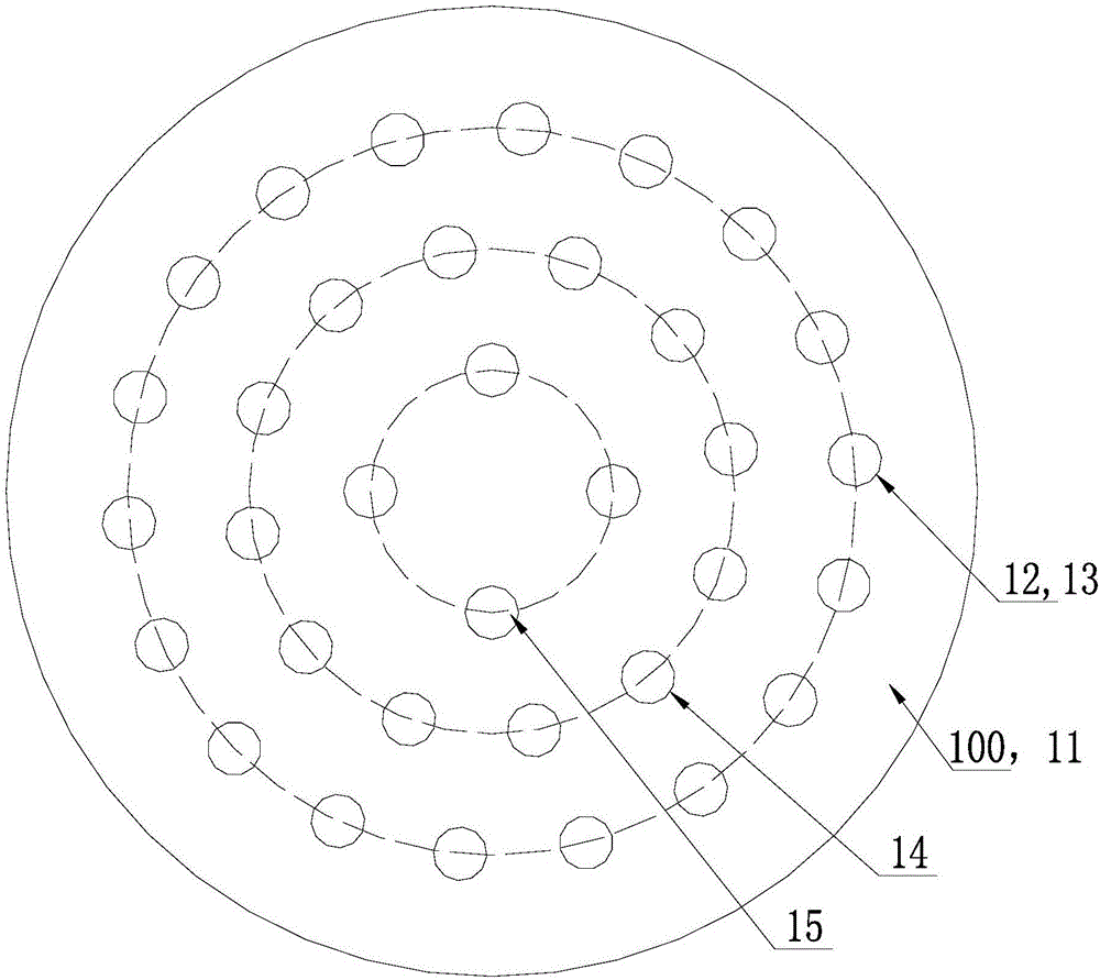
The invention relates to a reinforced-concrete draught fan tower. The reinforced-concrete draught fan tower comprises a pile foundation, a supporting platform, a concrete tower body and a steel tower body, wherein the pile foundation, the supporting platform, the concrete tower body and the steel tower body are sequentially arranged from bottom to top. The pile foundation is pre-buried underground, the supporting platform laid on the pile foundation is arranged at the bottom of the concrete tower body, the supporting platform and the pile foundation are integrally formed through pouring, and the top of the concrete tower body is coaxially and fixedly connected with the bottom of the steel tower body through a connecting part. The upper ends and the lower ends of prestressed steel bars penetrating through the side wall of the concrete tower body are fixed to the connecting part and the supporting platform correspondingly through anchors. Due to the arrangement, the draught fan tower which is overall high is divided into the concrete tower body and the steel tower body, so that the overall manufacturing cost of a draught fan is lowered; meanwhile, the upper ends and the lower ends of the prestressed steel bars penetrating into the concrete tower body are fixed through the anchors correspondingly, so that the prestressed steel bars are in a tensioned state, wind resistance and vibration reduction are provided for concrete steel bars, and shaking caused by pneumatic vibration of the tower is buffered.

Description

technical field [0001] The invention relates to a wind power generator in the field of electric power, in particular to a steel-concrete structure wind turbine tower. Background technique [0002] With the vigorous development of the wind power industry, the construction of onshore wind farms is becoming more and more saturated, and there are fewer and fewer places with good wind resources. Facing this urgent situation, it is undoubtedly the onshore wind farm to explore better wind resources. The direction of future development. [0003] The hybrid tower generally consists of two parts, the lower end is a concrete tower, and the upper end is a traditional steel tower. The hybrid tower can increase the height of the hub to more than 120 meters, which can increase the power generation of wind farms by 20%. Hybrid towers open up new dimensions for onshore wind farms. [0004] However, the height of the concrete tower itself is high, and the manufacturing process of the exist...

Claims


Application Information

Patent Timeline
IPC IPC(8): F03D13/20
CPCY02E10/72Y02E10/728Y02P70/50
Inventor 黄志军张军涛李如意陈涛张富立杨国栋
Owner DATANG HUBEI NEW ENERGY CO LTD
Learn More