Slender-rod pressure release valve

A technology of slender rods and pressure relief valves, which is applied in the direction of safety valves, balance valves, valve devices, etc., can solve the problems of being unsuitable for high temperature and low pressure occasions, easy fatigue, and large changes in spring load, so as to shorten the maintenance cycle, Cost reduction, good orientation effect

Active Publication Date: 2016-06-29
WUXI SWATER FLUID CONTROL TECH CO LTD
View PDF6 Cites 3 Cited by
  • Summary
  • Abstract
  • Description
  • Claims
  • Application Information

AI Technical Summary

Problems solved by technology

[0003] At present, the pressure relief valves that are often used mainly include bursting disc type, spring type, bursting needle type pressure relief butterfly valve and pilot plunger valve, etc. They all have their own advantages and disadvantages: 1. The bursting disc type cannot be reused, and the quality is not good. Hershey is easy to fatigue and cause failure, and it is troublesome to replace; 2. The spring load changes greatly with the rise of the valve disc, and its performance is greatly affected by high temperature; The pressure trigger mechanism is too complicated, the precision is not high, and the cost is too high; 4. The pilot-operated plunger valve is quite complicated, and it is directly connected with the main valve, which has limitations in use and is not suitable for high temperature and low pressure occasions

Method used


Image

  • Slender-rod pressure release valve
  • Slender-rod pressure release valve

Examples


Embodiment Construction

[0025] The present invention will be further described below in conjunction with specific drawings and embodiments.

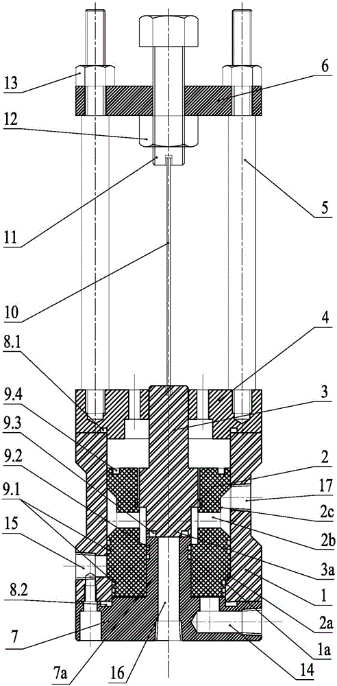
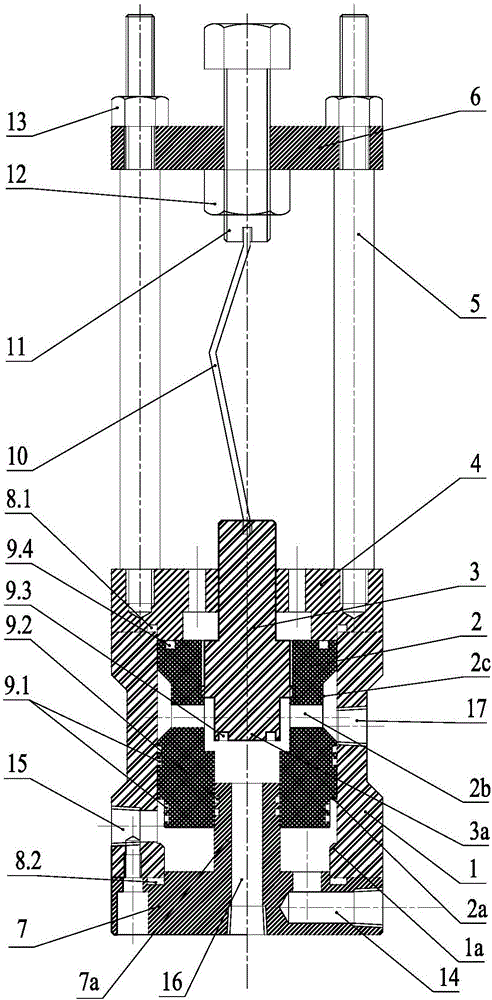
[0026] As shown in the figure: the slender rod pressure relief valve in the embodiment is mainly composed of a valve body 1, an upper valve cover 4, a bottom cover 7, a valve core 2, a valve rod 3 and a slender rod 10, etc., the valve body 1 It is a cylindrical body, the upper valve cover 4 is installed on the top of the valve body 1 by bolt sealing, and the bottom cover 7 is installed on the bottom of the valve body 1 by bolt sealing, and the upper valve cover 4, the valve body 1 and the bottom cover 7 form a A closed cylindrical cavity; the valve core 2 is assembled in the cylindrical cavity and can move up and down, the lower end of the valve stem 3 is connected to the valve core 2, and the upper end of the valve stem 3 passes through the central through hole of the upper valve cover 4 , the top of the stem 3 is connected to the lower end of a vertically arr...


PUM


Abstract

The invention relates to a slender-rod pressure release valve. A valve body is a cylinder; an upper valve cover is hermetically arranged on the top of the valve body; a bottom cover is hermetically arranged on the bottom of the valve body; the upper valve cover, the valve body and the bottom cover form a sealed cylindrical cavity; a valve element is assembled in the cylindrical cavity and can move up and down; the lower end of a valve rod is connected with the valve element, and the upper end of the valve rod passes through a central through hole of the upper valve cover; the top of the valve rod is connected with the lower end of a slender rod vertically arranged; the upper end of the slender rod is connected with a support rack; the support rack is fixedly connected with the upper valve cover; the bottom cover is provided with a medium high-pressure input passage; inner port of the medium high-pressure input passage is opposite to the bottom of the valve element; the valve body is provided with a medium low-pressure output passage; an inner port of the medium low-pressure output passage is positioned in an inner wall of the valve body; when the valve element is kept static, the inner port of the medium low-pressure output passage is plugged by the valve element; when the valve element moves upward, the inner port of the medium low-pressure output passage is opened. The slender-rod pressure release valve is wide in application range and high in adjustment precision.

Description

technical field [0001] The invention relates to a pressure relief valve, in particular to a slender rod pressure relief valve, which belongs to the technical field of valve equipment. Background technique [0002] With the development of industry and the progress of science and technology, people pay more and more attention to safety issues and have higher and higher requirements. In various occasions, more and more attention is paid to the use of pressure relief valves (safety valves). [0003] At present, the pressure relief valves that are often used mainly include bursting disc type, spring type, bursting needle type pressure relief butterfly valve and pilot plunger valve, etc. They all have their own advantages and disadvantages: 1. The bursting disc type cannot be reused, and the quality is not good. Hershey is easy to fatigue and cause failure, and it is troublesome to replace; 2. The spring load changes greatly with the rise of the valve disc, and its performance is...

Claims


Application Information

Patent Timeline
Patent Type & Authority Applications(China)
IPC IPC(8): F16K17/02
CPCF16K17/02
Inventor 宋尚
Owner WUXI SWATER FLUID CONTROL TECH CO LTD
Why Eureka
Try Eureka