
Device and method for in-situ observation of pore water pressure in shallow seas based on the principle of vibration liquefaction

A technology of pore water pressure and vibration liquefaction, which is applied in the direction of measuring devices, measuring fluid pressure, instruments, etc., can solve the problems of complex deployment operation, high cost of pore water pressure observation, hidden safety hazards, etc., and achieve simple deployment operation steps, The effect of saving observation cost and strong reusability

Active Publication Date: 2017-08-08
OCEAN UNIV OF CHINA
View PDF8 Cites 0 Cited by
  • Summary
  • Abstract
  • Description
  • Claims
  • Application Information

AI Technical Summary

Problems solved by technology

In the actual deployment process, the drilling method requires a drilling rig to be provided during the deployment of the pore water pressure observation system, which increases the cost of pore water pressure observation. To avoid shrinkage cavity or collapse in the hole forming process, this method is cumbersome to operate; the static pressure method often needs to provide a huge back pressure, which makes the deployment operation complicated, and cannot ensure that the probe maintains a vertical posture in the soil. certain security risks

Method used


Image

  • Device and method for in-situ observation of pore water pressure in shallow seas based on the principle of vibration liquefaction
  • Device and method for in-situ observation of pore water pressure in shallow seas based on the principle of vibration liquefaction
  • Device and method for in-situ observation of pore water pressure in shallow seas based on the principle of vibration liquefaction

Examples


Embodiment Construction

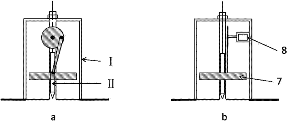
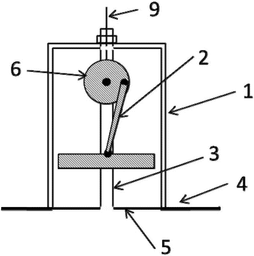
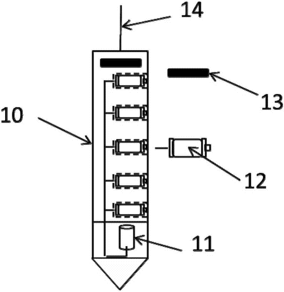
[0040] see figure 1 a. figure 1 b, An in-situ observation device for pore water pressure in shallow seas based on the principle of vibration liquefaction. Including liquefaction vibration device I and pore water pressure observation system II; figure 2, the liquefaction vibration device I includes a vibration box 1 and a piston vibration system; the vibration box 1 is a cylindrical structure, the bottom periphery is provided with an anti-sedimentation disc 4, and a series of drainage holes are opened on the surface of the anti-settling disc 4 for Release the suction formed by the contact between the anti-subsidence disc 4 and the seabed surface; a hollow casing 3 runs through the middle of the vibrating box 1, and the upper and lower ends of the casing 3 are open to protect the pore water pressure observation system II during deployment The bottom of the vibration box 1 of the liquefaction vibration device I and the casing 3 are connected with a water-permeable flexible mat...


PUM

PropertyMeasurementUnit
lengthaaaaaaaaaa

Abstract

The invention relates to a beach shallow sea pore water pressure in situ observation device and method based on a vibratory liquefaction principle. The beach shallow sea pore water pressure in situ observation device comprises a liquefaction vibration device and a pore water pressure observation system. The principle of the observation device comprises that seabed soil body is locally liquefied by virtue of the liquefaction vibration device in a laying process, strength of liquefied seabed soil body is lost, and the pore water pressure observation system is laid to designated depth under the action of gravity. The observation method comprises the following steps: carrying the pore water pressure in situ observation device to a target observation point by an auxiliary sheep; mounting and laying the liquefaction vibration device and the pore water pressure observation system to a seabed surface; and laying the pore water pressure observation system to the designated depth by virtue of the liquefaction vibration device, and realizing long-term in situ observation on seabed pore water pressure. The pore water pressure observation system is composed of a series of pore water pressure sensors and can realize continuous pore water pressure observation at different depths of the seabed. The detection device provided by the invention is simple in laying operation steps, low in cost and applicable to beach shallow area pore pressure in situ observation.

Description

technical field [0001] The invention relates to an in-situ observation device and method for shallow sea pore water pressure based on the principle of vibration liquefaction, and belongs to the technical field of marine observation and the field of marine engineering geology. Background technique [0002] Under the action of wave dynamics, the pore water pressure inside the seabed sediments is constantly changing dynamically, and the dynamic accumulation of pore water pressure will lead to a decrease in the effective normal stress of the seabed sediments, which will easily lead to seabed liquefaction and lateral deformation of the seabed, and even induce submarine landslides . The in-situ observation of pore water pressure can effectively reflect the dynamic geological process of the seabed, which is of great significance for the study of the dynamic response of seabed sediments under the action of waves and other hydrodynamic forces, and plays an important role in the effec...

Claims


Application Information

Patent Timeline
Patent Type & Authority Patents(China)
IPC IPC(8): G01L11/00
CPCG01L11/00
Inventor 贾永刚文明征郭磊王振豪刘晓磊张少同单红仙
Owner OCEAN UNIV OF CHINA
Learn More