Light beam generation device and method for generating visible boundary and electronic boundary system

A technology for generating devices and boundary systems, which is applied in the field of unmanned aerial vehicles and can solve problems such as failure to complete, ground control system disconnection, and risks

Inactive Publication Date: 2016-06-29
杨珊珊
View PDF9 Cites 4 Cited by
  • Summary
  • Abstract
  • Description
  • Claims
  • Application Information

AI Technical Summary

Problems solved by technology

However, in the above technical solution, when the UAV is far away from the ground control system, the signal is too weak, or when the signal transmission between the UAV and the ground control system is interfered, it is easy for the UAV positioning information to fail to be timely. If it is transmitted to the ground control system so that the above-mentioned boundary monitoring function cannot be completed, then the UAV will exceed the preset safety range and lose contact with the ground control system.
[0005] Therefore, based on the above-mentioned technical problems, the applicant has proposed an electronic boundary device to flexibly set boundaries for the flight activities of unmanned aerial vehicles, thereby conveniently establishing a no-fly area (protected area) or a site that allows flight On the basis of this patent application, the applicant found that there is still a technical problem: although there is an electronic boundary physically, this electronic boundary is completely based on wireless signals and is invisible
For example, there may be people who do not know the existence of the electronic border, thus intruding into the flying field originally designed for the activities of unmanned aerial vehicles, resulting in potential risks and threats

Method used


Image

  • Light beam generation device and method for generating visible boundary and electronic boundary system
  • Light beam generation device and method for generating visible boundary and electronic boundary system
  • Light beam generation device and method for generating visible boundary and electronic boundary system

Examples


Embodiment 1

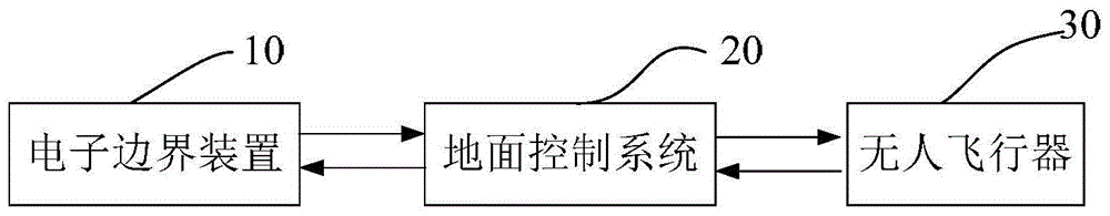
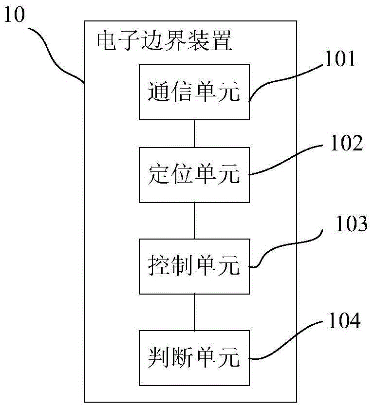
[0033] Figure 1a It is a schematic diagram of the basic composition of an electronic boundary system with a visible boundary according to an embodiment of the present invention; Figure 1b It is a schematic diagram of the basic composition of the electronic boundary device of this embodiment.

[0034] Such as Figure 1a As shown, the electronic boundary system includes an electronic boundary device 10, one or more unmanned aerial vehicles 30, and a ground control system 20, and the above-mentioned electronic boundary device 10 is set independently of the above-mentioned unmanned aerial vehicle 30 or the ground control system 20. In other words, the above-mentioned electronic boundary device 10 can be moved to any position according to specific needs, and the above-mentioned electronic boundary device can be placed at a predetermined position to determine the above-mentioned flight area. In addition, in this embodiment, the flying area of ​​the UAV 30 is determined based on th...

Embodiment 2

[0059] image 3 It is a schematic diagram of a light beam generating device for generating a visible boundary according to Embodiment 2 of the present invention.

[0060] Such as image 3 As shown, determining the flight area of ​​the UAV 30 based on the location information of the electronic boundary device 10 includes at least the following situations: the flight area of ​​the UAV 30 is generated with the location of the electronic boundary device 10 as the center or base point.

[0061] In an exemplary embodiment, the light source device includes a light source and a housing, which is arranged on the top of the electronic boundary device, emits the visible light beam obliquely downward, and projects it onto the ground to form a visible light beam of the flying area of ​​the UAV. view borders.

[0062] For example, the flight area of ​​the UAV 30 is set as a circle centered at the position of the electronic boundary device 10 and the radius is R. In this way, the area with...

Embodiment 3

[0072] Figure 4 It is a schematic diagram of a light beam generating device for generating a visible boundary according to Embodiment 3 of the present invention.

[0073] Such as Figure 4 As shown, the flight area Y of the unmanned aerial vehicle 30 takes the position of the above-mentioned electronic boundary device 10 and its extended surface as the boundary of the flight area, that is, the area located on either side of the position of the above-mentioned electronic boundary device 10 and its extended surface constitutes the above-mentioned unmanned aerial vehicle. Correspondingly, the other side constitutes the above-mentioned no-fly zone for unmanned aerial vehicles.

[0074] Correspondingly, the light source device can be arranged on the first side (for example, the left side) and / or the second side (for example, the right side) of the electronic boundary device 10, respectively for The left area and / or the right area of ​​the position where 10 is located and its ext...


PUM


Abstract

The invention mainly provides a light beam generating device for generating a visible boundary, an electronic boundary system and a method, and belongs to the field of unmanned aerial vehicles. The device includes: at least one light source device, which is arranged on the electronic boundary device, wherein the electronic boundary device is used to set the flight area of ​​the UAV, and the electronic boundary device is set independently of the UAV, and The flight area of ​​the unmanned aerial vehicle is determined based on the position information of the electronic boundary device; the light source device emits a visible light beam for prompting the range of the flight area. By adopting the above solution, the visible boundary of the flight area of ​​the UAV can be formed, which facilitates the onlookers to clearly know the scope of the flight area, and improves the flight safety of the UAV.

Description

Technical field: [0001] The invention mainly relates to the field of unmanned aerial vehicles, and in particular to a beam generating device, an electronic boundary system and a method for generating a visible boundary. Background technique: [0002] Unmanned aircraft, referred to as unmanned aerial vehicle (UAV), is a new concept of flying equipment in rapid development. Etc. Unmanned aerial vehicles are equipped with multiple types of sensors, which can realize real-time image transmission, detection of high-risk areas, etc., and at present, the scope of use of unmanned aerial vehicles has been expanded to three major fields: military, scientific research, and civilian use, and has a wide range of applications. [0003] However, although the existing unmanned aerial vehicle can achieve long-term and long-distance target detection or target tracking operations, but because its flight area may not have been set in detail, the unmanned aerial vehicle may exist during flight....

Claims


Application Information

Patent Timeline
Patent Type & Authority Applications(China)
IPC IPC(8): G05D1/10
CPCG05D1/10
Inventor 杨珊珊
Owner 杨珊珊
Why Eureka
Try Eureka