
Permanent magnetic vacuum on-load voltage regulation switch, transformer and on-load voltage regulation method

A voltage regulating switch and permanent magnet vacuum technology, applied in the field of transformer voltage regulation, can solve the problems of reducing switch life, reducing insulation resistance, increasing leakage current, etc., and achieve the effects of avoiding carbonization of oil, improving reliability and low failure probability

Active Publication Date: 2016-06-29
BEIJING PINGKAI INTELLIGENT ELECTRIC
View PDF7 Cites 7 Cited by
  • Summary
  • Abstract
  • Description
  • Claims
  • Application Information

AI Technical Summary

Problems solved by technology

Existing on-load voltage regulation switches are all carried out under electrified conditions, and the on-load voltage regulation operation will generate arcs. If the on-load voltage regulation is carried out frequently under the charged condition for a long time, frequent arcs will deteriorate the oil quality inside the switch The deterioration of oil quality will produce free carbon, hydrogen, acetylene and other gases and oil dirt. Some of the free carbon particles and oil dirt will be mixed in the insulating oil and accumulate on the surface of the insulating part of the switch to form deposits. The increase of deposits will increase Leakage current reduces insulation resistance and eventually leads to abnormal discharge, requiring frequent maintenance, increasing work intensity and reducing switch life

Method used


Image

  • Permanent magnetic vacuum on-load voltage regulation switch, transformer and on-load voltage regulation method
  • Permanent magnetic vacuum on-load voltage regulation switch, transformer and on-load voltage regulation method
  • Permanent magnetic vacuum on-load voltage regulation switch, transformer and on-load voltage regulation method

Examples


Embodiment Construction

[0039] The following will clearly and completely describe the technical solutions in the embodiments of the present invention with reference to the accompanying drawings in the embodiments of the present invention. Obviously, the described embodiments are only some, not all, embodiments of the present invention. The components of the embodiments of the invention generally described and illustrated in the figures herein may be arranged and designed in a variety of different configurations. Accordingly, the following detailed description of the embodiments of the invention provided in the accompanying drawings is not intended to limit the scope of the claimed invention, but merely represents selected embodiments of the invention. Based on the embodiments of the present invention, all other embodiments obtained by those skilled in the art without making creative efforts belong to the protection scope of the present invention.

[0040] It should be noted that like numerals and let...


PUM


Abstract

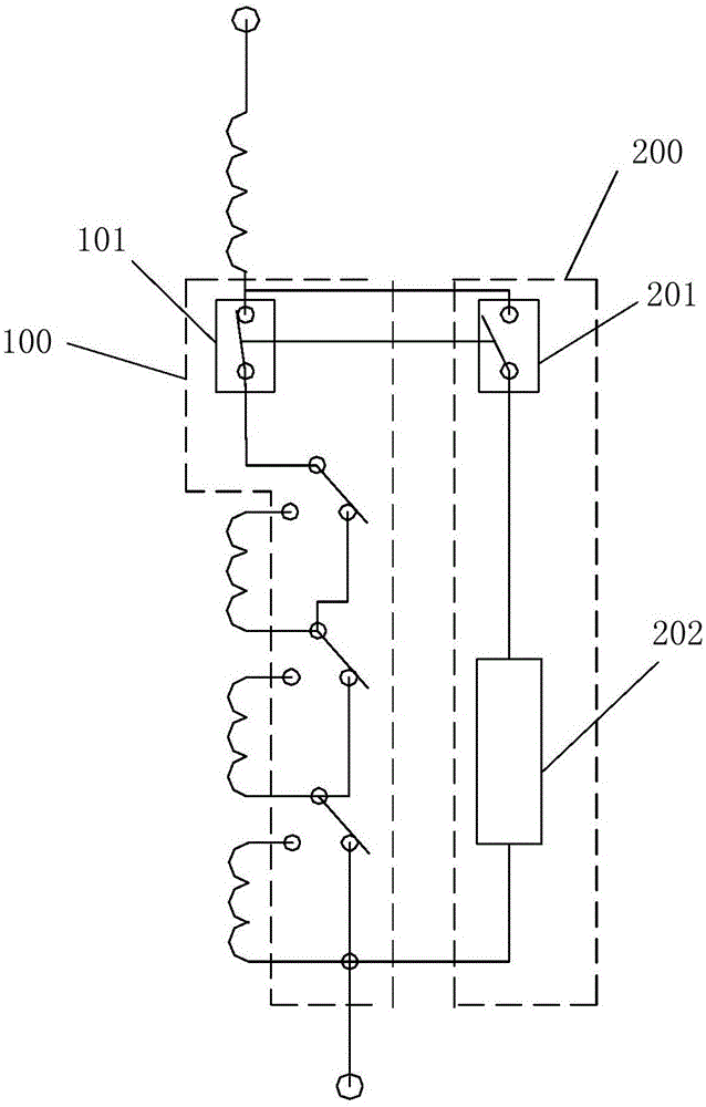
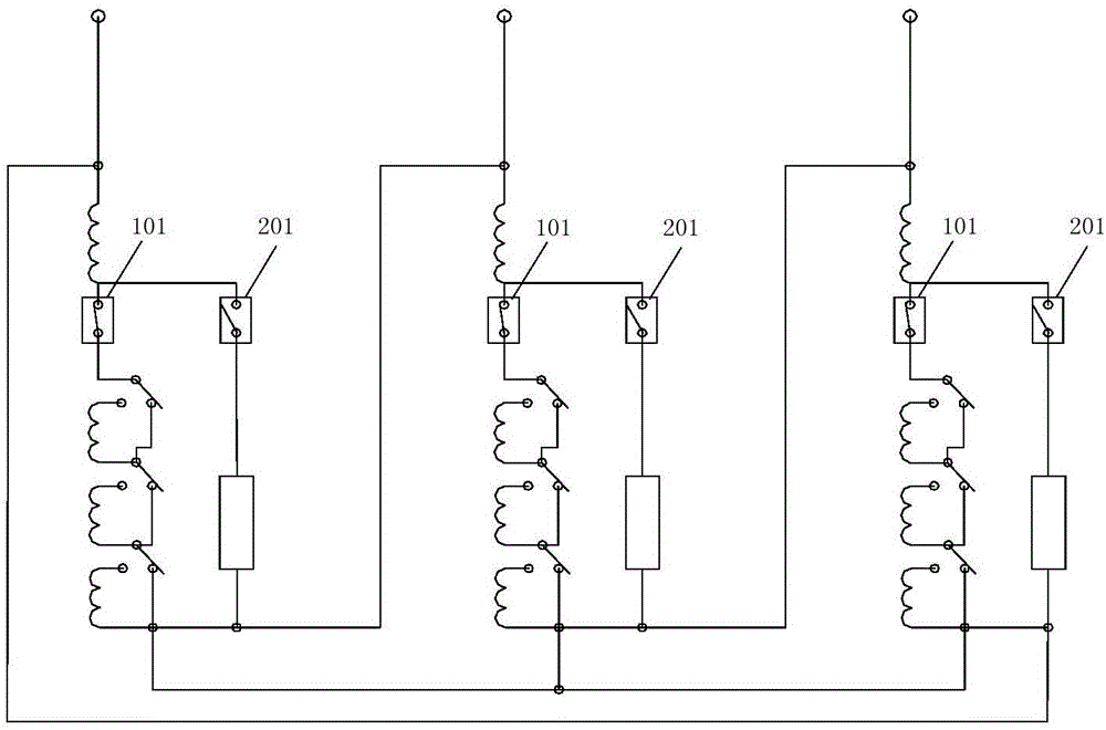
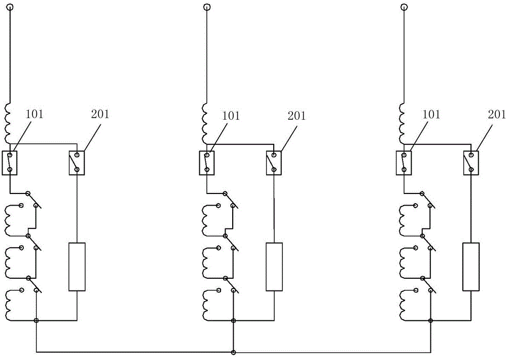
The invention provides a permanent magnetic vacuum on-load voltage regulation switch which is used for carrying out on-load voltage regulation on a three-phase transformer. The permanent magnetic vacuum on-load voltage regulation switch comprises a three-phase voltage regulation main loop and a three-phase voltage regulation transition loop; and a voltage regulation switch is also arranged on the voltage regulation main loop. The voltage regulation switch adopts a permanent magnetic mechanism, does not need to use a power mechanism, has a simpler structure and is more convenient to operate. A fault probability is lower, and reliability is improved. A main loop switch and a transition loop switch are vacuum switches and an electric arc cannot be generated in the on-load voltage regulation process, so that the defect of oil carbonization caused by the electric arc is avoided, a user does not need to regularly carry out overhauling maintenance and oil filtration, and non maintenance is achieved. Only six vacuum arc-extinguishing chambers are adopted, so that the switch is smaller in volume and lower in cost. Moreover, the numbers of turns of coils corresponding to transformer taps are set proportionally, so that under the requirement of the same voltage regulation gear number, the number of the transformer taps can be reduced to the greatest extent and wiring can be simplified.

Description

technical field [0001] The invention relates to the field of transformer voltage regulation, in particular to a permanent magnet vacuum on-load voltage regulation switch, a transformer and an on-load voltage regulation method. Background technique [0002] Transformer voltage regulation is to adjust the tap of the coil on one side of the transformer through the voltage regulating switch to change the number of turns of the coil to achieve the purpose of changing the output voltage. On-load voltage regulation means not disconnecting the power supply, so that the transformer can adjust the voltage regulating switch with load under normal working conditions. Existing on-load voltage regulation switches are all carried out under electrified conditions, and the on-load voltage regulation operation will generate arcs. If the on-load voltage regulation is carried out frequently under the charged condition for a long time, frequent arcs will deteriorate the oil quality inside the sw...

Claims


Application Information

Patent Timeline
Patent Type & Authority Applications(China)
IPC IPC(8): H01F29/04H01H9/00
CPCH01F29/04H01H9/0038
Inventor 魏晓熙
Owner BEIJING PINGKAI INTELLIGENT ELECTRIC
Learn More