Dynamic random access memory

A dynamic random access and memory technology, applied in transistors and other directions, can solve problems such as component interference, and achieve the effect of reducing component area

Active Publication Date: 2016-06-29
WINBOND ELECTRONICS CORP
View PDF4 Cites 0 Cited by
  • Summary
  • Abstract
  • Description
  • Claims
  • Application Information

AI Technical Summary

Problems solved by technology

[0004] However, the above-mentioned DRAM still has room for reduction, and the lines with increasingly smaller pitches will also cause the problem of interference between components when operating components.

Method used


Image

  • Dynamic random access memory
  • Dynamic random access memory
  • Dynamic random access memory

Examples


Embodiment Construction

[0034] In order that the concept of the invention may be more fully appreciated, reference is made herein to the accompanying drawings, in which embodiments of the invention are shown. However, the invention may also be practiced in many different forms and should not be construed as limited to the embodiments set forth below. Rather, the embodiments are provided only so that the present disclosure will be thorough and complete, and will fully convey the scope of the present invention to those skilled in the art.

[0035] In the drawings, the size and relative sizes of layers and regions may be exaggerated for clarity.

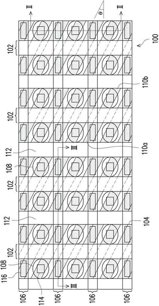
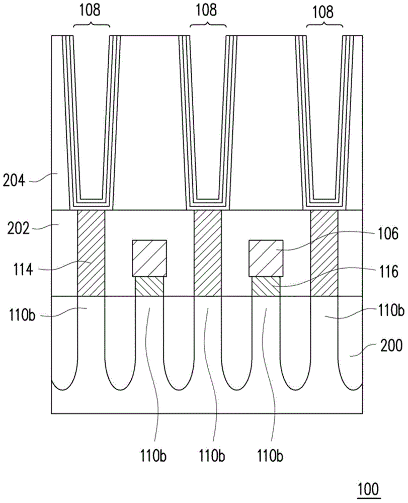
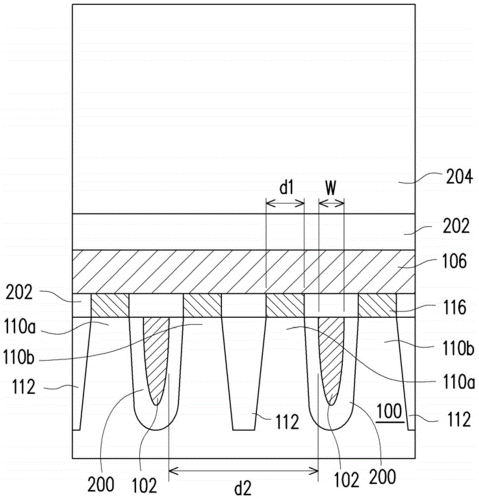
[0036] figure 1 It is a schematic layout diagram of a dynamic random access memory according to an embodiment of the present invention; figure 2 yes figure 1 The schematic cross-sectional view of the II-II line segment; image 3 yes figure 1 Schematic cross-section of the III-III line segment.

[0037] Please refer to Figure 1~3 , the DRAM of this emb...


PUM


Abstract

The invention provides a dynamic random access memory, comprising a substrate, buried word lines and active areas which are positioned in the substrate, bit lines and capacitors. The long edge directions of the active areas and the extension directions of the bit lines form acute angles theta, and the bit lines are positioned on the substrate and cross the buried word lines. Each buried word line divides the active areas arranged on the same column into two contact areas, and each bit line is electrically connected with the adjacent contact areas on two sides of each buried word line. The capacitors are arranged between the bit lines, and each capacitor is electrically connected with the adjacent contact areas on two sides of each buried word line. Thus, in each active area, one contact area is electrically connected with one capacitor, while the other contact area is electrically connected with one bit line.

Description

technical field [0001] The present invention relates to a dynamic random access memory (Dynamic Random Access Memory, referred to as DRAM), and in particular to a dynamic random access memory capable of reducing the area of ​​components. Background technique [0002] In order to improve the integration level of DRAM, speed up the operation speed of components, and meet the needs of consumers for miniaturized electronic devices, a buried word line DRAM (buried wordline DRAM) has been developed in recent years to meet the above-mentioned requirements. Various needs. [0003] For example, for reducing the area of ​​the device, there is currently an embedded word line DRAM designed by developing word lines, active regions and bit lines with different extending directions. [0004] However, the above-mentioned DRAM still has room for reduction, and the circuits with increasingly smaller pitches will also cause the problem of interference between components when operating the com...

Claims


Application Information

Patent Timeline
IPC IPC(8): H01L27/108
Inventor 林志豪
Owner WINBOND ELECTRONICS CORP
Why Eureka
Try Eureka