
Terminal antenna based on ceramic back shell and terminal equipment

A terminal antenna and terminal equipment technology, applied in antennas, resonant antennas, electrical short antennas, etc., can solve the problems of limited installation of terminal antennas, affecting the development of terminal equipment, and limited space for terminal equipment, so as to facilitate development and increase Space utilization and the effect of reducing the space occupied by installation

Inactive Publication Date: 2016-06-29
ORA INC
View PDF2 Cites 0 Cited by
  • Summary
  • Abstract
  • Description
  • Claims
  • Application Information

AI Technical Summary

Problems solved by technology

[0003] The embodiment of the present invention provides a terminal antenna and terminal equipment based on a ceramic back shell, which is used to solve the problem in the prior art that due to the limited space of the terminal equipment, the installation of the terminal antenna is limited, which affects the development of the terminal equipment.

Method used


Image

  • Terminal antenna based on ceramic back shell and terminal equipment
  • Terminal antenna based on ceramic back shell and terminal equipment

Examples


Embodiment Construction

[0014] The technical content of the present invention will be described in detail below by taking a terminal device whose back shell material is a ceramic material as an example.

[0015] Those skilled in the art should understand that, for the sake of brevity, only the core technical solution of the present invention is described in the following embodiments, but any part related to the prior art will not be described in detail.

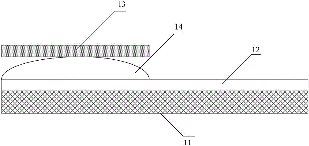
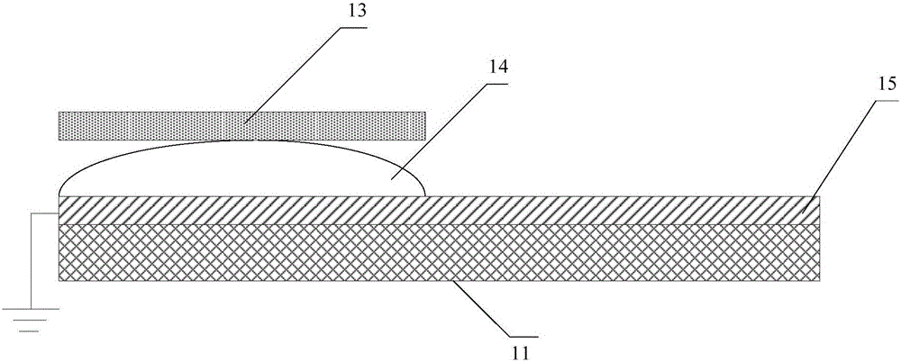
[0016] figure 1 A schematic structural diagram of a terminal antenna provided for an embodiment of the present invention, as shown in figure 1 As shown, the terminal antenna provided in this embodiment includes the following structure:

[0017] A terminal ceramic back shell 11 used as a dielectric resonator and a coplanar waveguide 12 fixed on the ceramic back shell 11, the coplanar waveguide 12 is connected to the signal output end of the wireless communication module 13;

[0018] The coplanar waveguide 12 is used to transmit the signal output by...


PUM


Abstract

The embodiment of the invention provides a terminal antenna based on a ceramic back shell and terminal equipment. The terminal antenna comprises the terminal ceramic back shell used as a dielectric resonator and a coplanar waveguide fixedly arranged on the ceramic back shell; the coplanar waveguide is connected with a signal output end of a wireless communication module; and the coplanar waveguide is used for transmitting a signal output by the wireless communication module to the ceramic back shell so as to enable the ceramic back shell to radiate out the signal. The terminal antenna based on the ceramic back shell and the terminal equipment which are provided by the embodiment of the invention solve the problems of limitation to installation of the terminal antenna and influence on development of the terminal equipment, which are caused by a limited space of the terminal equipment in the prior art.

Description

technical field [0001] Embodiments of the present invention relate to the field of communication technologies, and in particular, to a terminal antenna and terminal equipment based on a ceramic back shell. Background technique [0002] With the development of smart devices, the network service functions of smart devices are increasingly powerful. In the prior art, various network service functions of smart devices are mainly realized through network antennas matched with each network service. For example, when a user uses a WIFI network for network Wireless and wireless networks are connected to realize information interaction between users and the network. However, with the powerful functions of smart devices, the number of antennas used to complete various wireless functions inside the device is increasing day by day, and the antenna itself has specific requirements for the internal space of the device, which makes the already tight device space become Even more embarras...

Claims


Application Information

Patent Timeline
Patent Type & Authority Applications(China)
IPC IPC(8): H01Q1/36H01Q9/04
CPCH01Q1/36H01Q9/04H01Q9/0407H01Q9/0442
Inventor 刘宁民
Owner ORA INC
Learn More