Dynamic calibration test bench of force measurement wheel pair

A force measuring wheelset and dynamic calibration technology, applied in the field of rail transit, can solve the problems of low work efficiency, inaccurate analysis of final results, complex structure, etc., and achieve the effect of small installation space, automatic calibration, and easy operation.

Active Publication Date: 2017-07-04
SOUTHWEST JIAOTONG UNIV
View PDF6 Cites 4 Cited by
  • Summary
  • Abstract
  • Description
  • Claims
  • Application Information

AI Technical Summary

Problems solved by technology

[0004] Chinese patent document CN102564690A discloses a new type of dynamic calibration test bench for force-measuring wheelsets. The dynamic calibration test bench for force-measuring wheelsets includes a calibration platform bearing base as the support base for other components, and is arranged on the calibration platform bearing base. The gantry assembly for fixedly installing the force-measuring wheel set, and the wheel-set clamping and limiting device arranged on the gantry assembly for positioning the force-measuring wheel set, the wheel-set clamping and limiting device has The mechanism for adjusting and positioning the force-measuring wheel set at least includes a loading gantry structure capable of steplessly positioning the force-measuring wheel set laterally along the bearing base of the calibration platform. In this patent, it is used to adjust and position the force-measuring wheel set The mechanism of the wheel set is manual, which has a great influence on the calibration results
Although the wheel set rotation indexing system in the prior art can make the wheel set rotate to any angle for loading, the calibration of the force-measuring wheel set can only be carried out in a static state, and its disadvantage is that the calibration data lacks continuity. Inaccurate analysis of the final results. In addition, the dynamic calibration test bench for force-measuring wheel sets in the above-mentioned prior art is bulky and complex in structure, resulting in low degree of automation of the device, low work efficiency, and cumbersome installation and disassembly procedures.

Method used


Image

  • Dynamic calibration test bench of force measurement wheel pair
  • Dynamic calibration test bench of force measurement wheel pair
  • Dynamic calibration test bench of force measurement wheel pair

Examples


Embodiment Construction

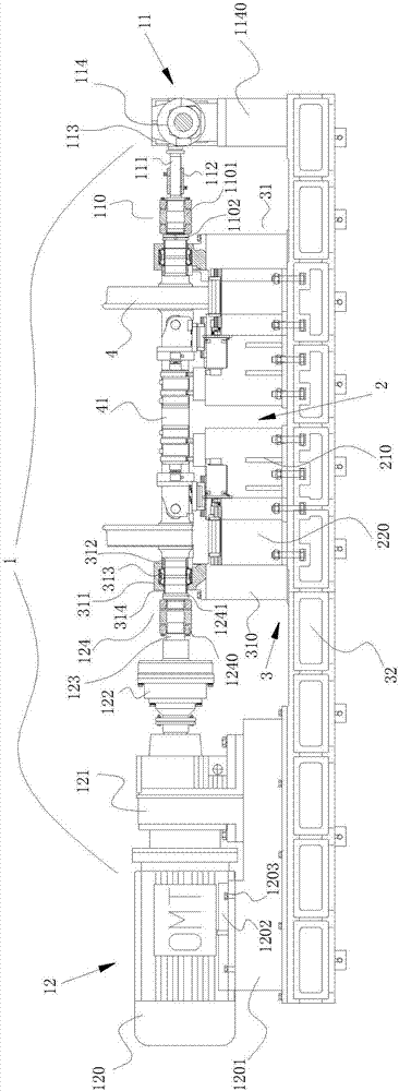
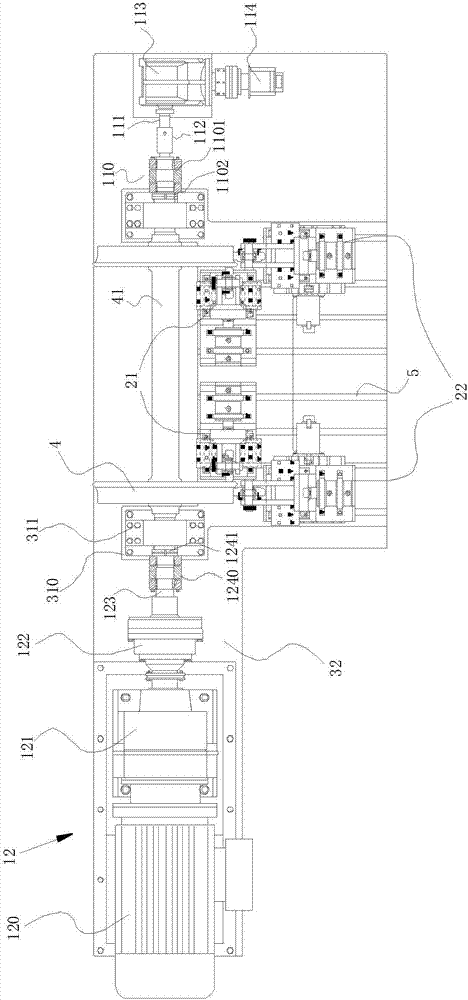
[0021] Such as figure 1 As shown, the dynamic calibration test bench of the force-measuring wheel set of the present invention includes a loading system 2 for loading the force-measuring wheel set 4, a support system 3 for supporting the force-measuring wheel set 4 and the loading system 2, and also includes a force-measuring wheel set The power system 1 in which the force wheel pair 4 is switched between the static calibration state and the dynamic calibration state. In the static calibration state, the power system 1 can make the force measuring wheel pair 4 rotate to any angle for loading. In the dynamic calibration state, the power The system 1 can make the force measuring wheel 4 rotate continuously at a low speed for loading. The support system 3 includes a support frame 31 supporting the two axial ends of the force-measuring wheel pair 4 and a base 32 arranged at the bottom of the support frame 31 for the installation of the loading system 2 , and the support frame 31 i...


PUM


Abstract

The invention relates to the technical field of rail transit, and discloses a dynamic calibration test bench of a force measurement wheel pair. The test bench comprises a loading system for carrying out loading on the force measurement wheel pair, a support system for supporting the force measurement wheel pair and the loading system, and a power system for allowing the force measurement wheel pair to be switched between a static calibration state and a dynamic calibration state. In the static calibration state, the power system can allow the force measurement wheel pair to rotate to any angle for loading. In the dynamic calibration state, the power system can allow the force measurement wheel pair to continue to rotate at a low speed for loading. According to the invention, switching of the force measurement wheel pair between a dynamic loading test and a scale division loading test is achieved; data calibrated under dynamic loading is well continuous; the final result analysis is quite precise; and scale division loading of the force measurement wheel pair in the static state is also kept.

Description

technical field [0001] The invention relates to the technical field of rail transit, in particular to a dynamic calibration test bench for a force-measuring wheel set. Background technique [0002] The dynamic calibration test bench for force-measuring wheelsets is the key equipment to ensure the accuracy of wheel-rail force measurement. The precise calibration of the dynamometer wheel set on the test bench can determine the sensitivity of the dynamometer wheel set and effectively eliminate the coupling interference of lateral and longitudinal forces. [0003] Most of the dynamic calibration test benches for force-measuring wheelsets in the prior art are composed of three major systems: mechanical system, hydraulic loading system, electric control and measurement and control system. The mechanical system includes a base, a mast, and a wheelbase adjustment mechanism. The loading system includes any one or more of a longitudinal loading device, a lateral loading device, and a...

Claims


Application Information

Patent Timeline
Patent Type & Authority Applications(China)
IPC IPC(8): G01L25/00
CPCG01L25/00
Inventor 陈建政任愈张春开高杰维
Owner SOUTHWEST JIAOTONG UNIV
Why Eureka
Try Eureka