Dynamic output feedback controller for time-delay power system based on LMI

A power system, dynamic output technology, applied in electrical components, circuit devices, AC network circuits, etc., can solve problems such as difficulty in solving state variables and solving non-convex optimization conservatism

Inactive Publication Date: 2016-06-29
HENAN POLYTECHNIC UNIV
View PDF3 Cites 6 Cited by
  • Summary
  • Abstract
  • Description
  • Claims
  • Application Information

AI Technical Summary

Problems solved by technology

[0005] The purpose of the present invention is to provide a dynamic output feedback controller of time-delay power system based on LMI, to solve the problem

Method used


Image

  • Dynamic output feedback controller for time-delay power system based on LMI
  • Dynamic output feedback controller for time-delay power system based on LMI
  • Dynamic output feedback controller for time-delay power system based on LMI

Examples


Embodiment Construction

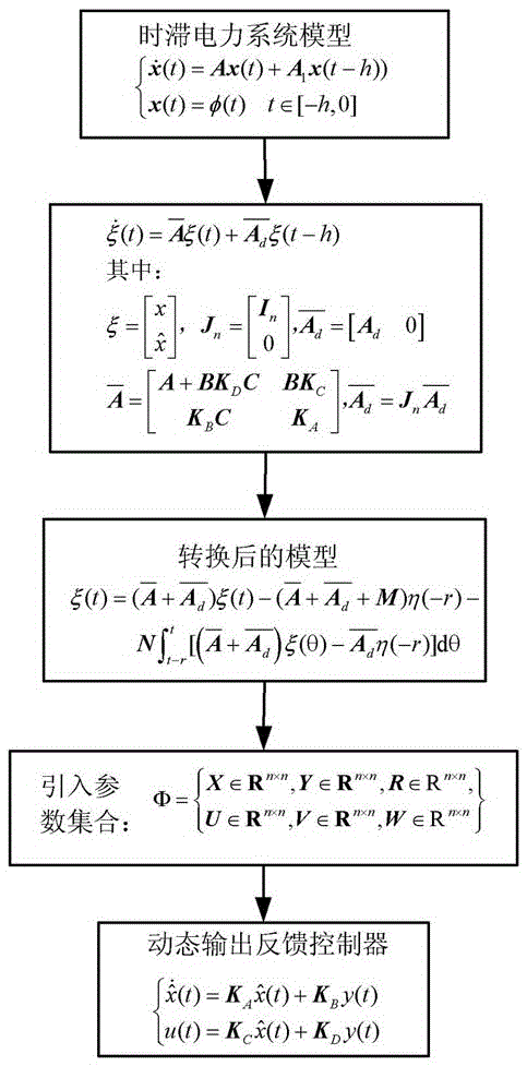
[0074] 1. Time-delay power system model:

[0075] The present invention considers the power system model as the following fourth-order differential equation based on the LMI time-delay power system dynamic output feedback controller, and assumes that there is a certain delay in the output voltage of the excitation system, then the system equation can be expressed as:

[0076] δ · = ω B ω ω · = P m - P G ...


PUM


Abstract

The invention relates to a dynamic output feedback controller for a time-delay power system based on an LMI. Firstly, a time-delay power system state space model is built; the dynamic output feedback controller is given to the time-delay power system state space model; suitable conversion is carried out to a closed-loop system by utilizing a free parameter matrix; the existence criterion of the controller of the time-delay power system is obtained through combination of a Lyapunov-Krasovskii function; and then the solutions of a controller parameter and a functional parameter are resolved into a linear matrix inequality form through adoption of a parameterized method. According to the controller provided by the invention, the conservative property resulting from solving a non-convex optimization problem is overcome; a simulation result indicates that the dynamic output controller has certain time-delay insensitivity; and the stability of the power system is improved.

Description

technical field [0001] The invention belongs to the technical field of power system controller design, in particular to an LMI-based time-delay power system dynamic output feedback controller. Background technique [0002] With the continuous development of the grid scale and the wide application of wide-area measurement technology in the power system, the time lag of information transmission in the modern power system can reach tens or even hundreds of milliseconds, and the time lag will seriously affect the stable operation of the power system. How to eliminate this adverse effect has become a hot research topic for domestic and foreign scholars. [0003] Linear Matrix Inequality (LMI) is one of the main methods for designing time-delay power system controllers, and many literatures have conducted in-depth research on this problem. For example, "Design of Memoryless State Feedback Controller for Time-Delay Power System Based on LMI Theory" (An Haiyun, Jia Hongjie, Yu Xiao...

Claims


Application Information

Patent Timeline
IPC IPC(8): H02J3/00
CPCH02J3/00H02J2203/20
Inventor 钱伟高超赵运基黄凯征李冰锋
Owner HENAN POLYTECHNIC UNIV
Why Eureka
Try Eureka