Method and apparatus for compressing/loading stent-valves

A technology for compressing devices and valves, used in stents, heart valves, medical science, etc.

Inactive Publication Date: 2016-06-29
SYMETIS
View PDF11 Cites 7 Cited by
  • Summary
  • Abstract
  • Description
  • Claims
  • Application Information

AI Technical Summary

Problems solved by technology

Additional complications also arise when the stent-valve is compressed for loading into a delivery catheter with multiple sheaths enclosing the stent-valve in different directions
These sheaths limit the space and means available to compress the stent-valve

Method used


Image

  • Method and apparatus for compressing/loading stent-valves
  • Method and apparatus for compressing/loading stent-valves
  • Method and apparatus for compressing/loading stent-valves

Examples


Embodiment Construction

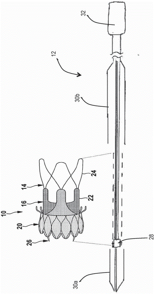
[0077] Before describing the compression device in detail, an example of a stent (stent-valve) is first described so that the characteristics and functions of the compression device can be fully understood.

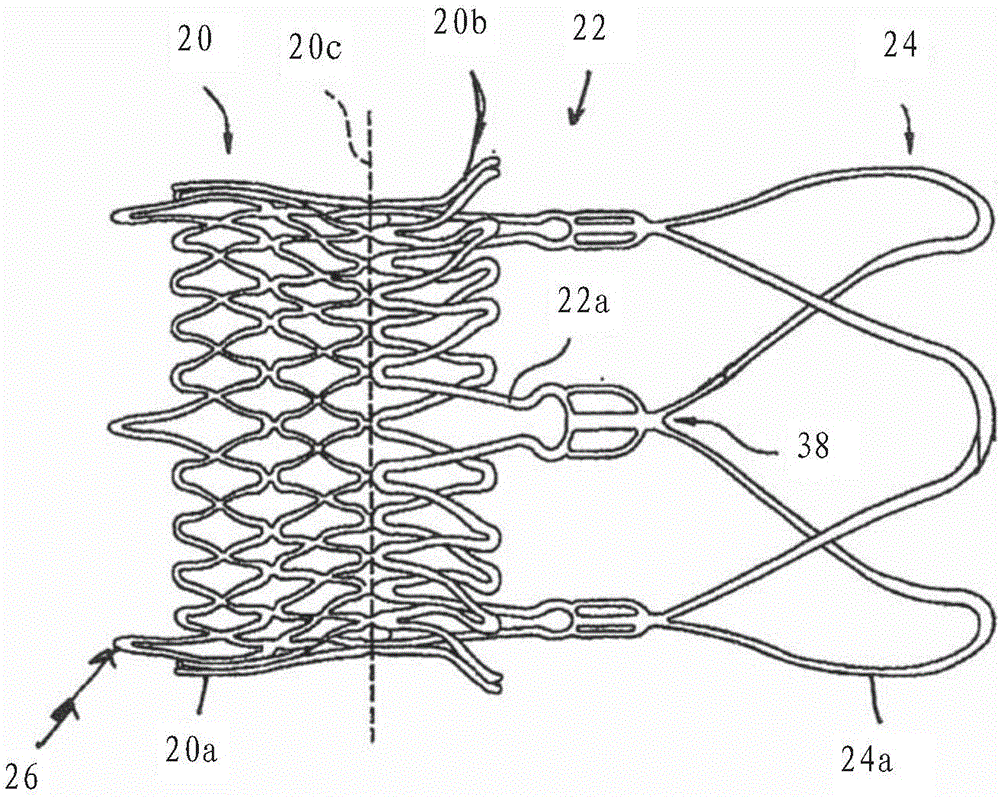
[0078] figure 1 and figure 2 An exemplary stent in the form of a stent-valve 10 is shown. The stent-valve 10 may be a cardiac stent-valve, such as an aortic stent-valve. Stent-valve 10 may be configured to allow transcatheter implantation in vivo, eg, to allow the use of minimally invasive techniques. Stent-valve 10 may be configured for transcatheter aortic valve implantation (TAVI). Although a particular geometry of the stent-valve 10 is shown by way of example, it is to be understood that the present invention is not limited to any particular stent-valve geometry. The example geometry is used here because it highlights the advantages of the invention.

[0079] Stent-valve 10 can be in expanded state (as figure 1 shown) and the compressed state shown by dashed li...


PUM


Abstract

Apparatus (40) for compressing a transcatheter cardiac stent-valve (10) comprises: a first compressor stage (100) including a hollow channel (42) with a tapered interior surface configured for compressing a stent-valve in response to longitudinal advancement of the stent-valve within the channel; and a second compressor stage (102) comprising a crimper for compressing a portion of the stent-valve without longitudinal advancement.

Description

technical field [0001] The present invention relates to the field of stents for transcatheter delivery, and in particular to methods and devices for compressing stents into a compressed state and / or loading stents into delivery catheters. In some non-limiting aspects, the stent is a stent-valve, such as a cardiac stent-valve. While the present invention aims to solve the problems associated with stent-valve, the present invention is also applicable to compressing other types of stents for transcatheter delivery. Background technique [0002] WO-A-2012 / 038550 describes a cardiac stent-valve and a system for percutaneous delivery of the stent-valve. The stent-valve is compressible to a compressed state adapted to be contained within a complementary sheath at the delivery tip of the delivery catheter. In the compressed state, the smaller size allows the catheter to be entered percutaneously and advanced via the femoral artery to reach the heart. The two sheaths cover differe...

Claims


Application Information

Patent Timeline
Patent Type & Authority Applications(China)
IPC IPC(8): A61F2/24B25B27/02A61F2/95A61F2/97
CPCA61F2/2418A61F2/97A61F2220/0008A61F2230/0054A61F2250/0018A61F2250/0091A61F2/2436A61F2/9522
Inventor L·曼塔那斯F·隆巴迪P·西莫南Y·比阿迪拉J-L·赫弗堤S·迪拉罗耶
Owner SYMETIS
Why Eureka
Try Eureka