
Earthworking tool and method for earthworking

A technology of work and equipment, which is applied in the direction of earth drilling, drilling equipment and methods, earth movers/shovels, etc., can solve the problems of time, operation and cost intensive, and achieve the improvement of operation accuracy and high efficiency of soil engineering. Operation, collision avoidance effect

Inactive Publication Date: 2016-06-29
BAUER SPEZIALTIEFBAU
View PDF11 Cites 4 Cited by
  • Summary
  • Abstract
  • Description
  • Claims
  • Application Information

AI Technical Summary

Problems solved by technology

However, these additional measures proved to be time, labor and cost intensive

Method used


Image

  • Earthworking tool and method for earthworking
  • Earthworking tool and method for earthworking
  • Earthworking tool and method for earthworking

Examples


Embodiment Construction

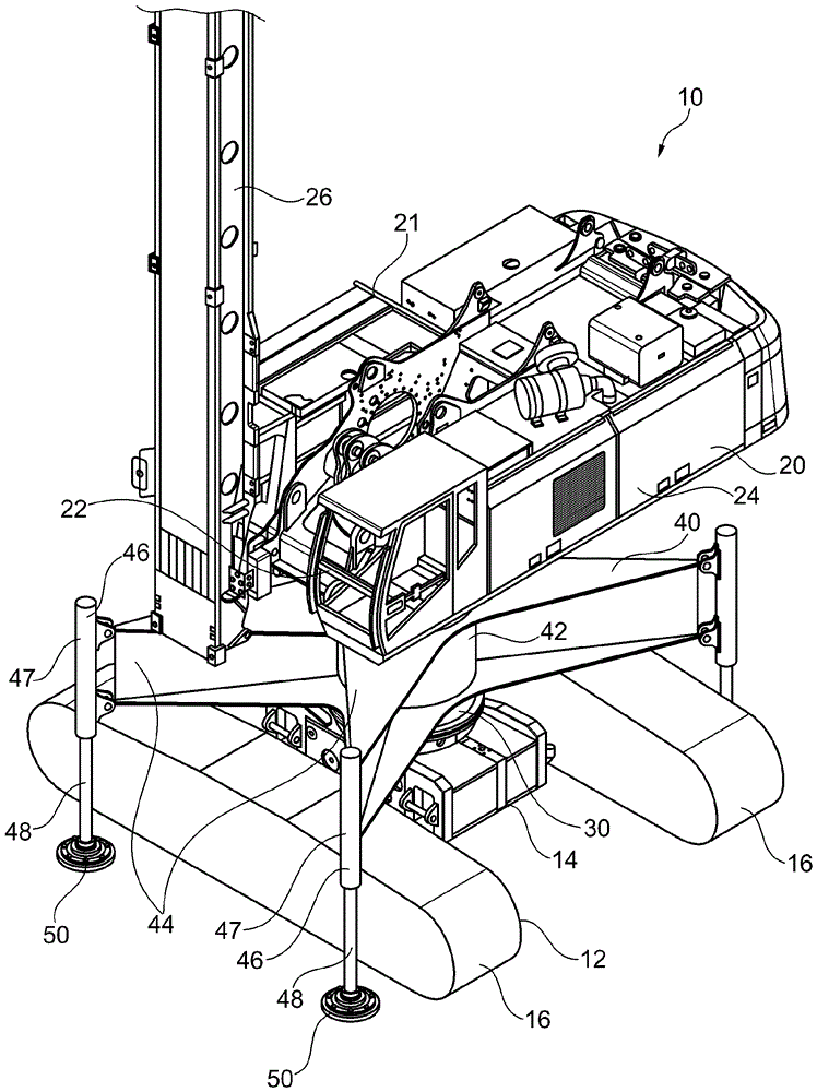
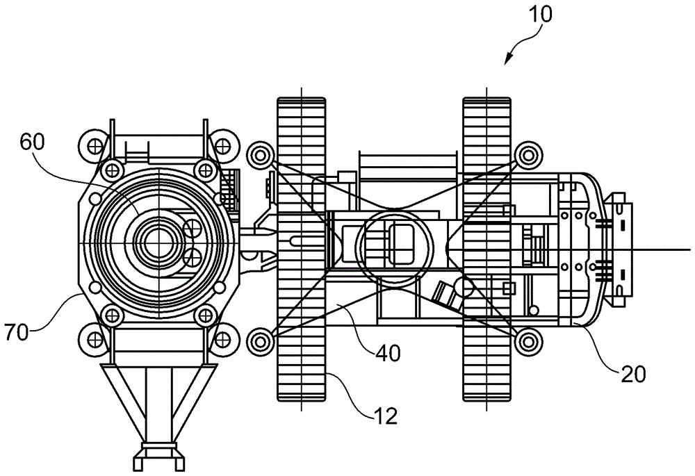
[0030] according to figure 1 , according to the earth working equipment 10 of the present invention has an underframe 12, and the underframe 12 is designed as a crawler running gear. On the central carrier frame 14 of the undercarriage 12 , track units 16 are arranged transversely in each case in a known manner. Above the bottom frame 12, an upper frame 20 is supported in the horizontal direction in a rotatable manner.

[0031] The upper frame 20 has a base frame 21 to the front side of which a vertical pole 26 is pivotably linked. Furthermore, on the front side of the upper frame 20 , a cab 22 is provided for operating the earth working equipment 10 . Furthermore, on the base frame 21 of the upper frame 20, a drive unit (in particular a drive motor for the underframe 12), a winch and hydraulic components are arranged. These units are housed within a housing 24 of the upper shelf 20 . in accordance with figure 1 In the illustration, the winches and hydraulic positioning c...


PUM


Abstract

The invention relates to an earthworking tool, comprising an undercarriage, which is disposed as a chassis, and a superstructure, which is rotatably mounted on the undercarriage and which has a driver compartment and a drive motor for the undercarriage. A extension segment is arranged between the undercarriage and the superstructure, by means of which a vertical distance between the undercarriage and the superstructure can be extended. A support device to prevent tipping is provided on the extension segment between the undercarriage and the superstructure. The invention further relates to a method for earthworking by means of such an earthworking device.

Description

technical field [0001] The invention relates to an earth-working machine according to the preamble of claim 1 , which has an undercarriage designed as a running gear and an upper frame which is rotatably mounted supported on the underframe and having a cab and a drive motor for the underframe. [0002] The invention also relates to a method for earth work according to the preamble of claim 11 , wherein auxiliary means are arranged on the ground around the working position, said auxiliary means having a predetermined height relative to the ground surface. Background technique [0003] General earth working equipment is known from eg EP1418152A1 or DE10360918B3. [0004] On the rotatable upper frame, the mast with the movable drill drive is arranged on the front side, while on the opposite lying rear area of ​​the upper frame, the main drive motor and further drive unit are provided for counterweight. Furthermore, support feet can be mounted on the upper frame so that the ea...

Claims


Application Information

Patent Timeline
IPC IPC(8): E02F9/02E02F9/12E21B7/02
CPCE21B7/024E02D17/13E02F3/205E21B7/02E21B43/10
Inventor S.施普赖策尔
Owner BAUER SPEZIALTIEFBAU
Learn More