Elevator door plate production line

A production line and door panel technology, applied in storage devices, metal processing equipment, feeding devices, etc., can solve the problems of incoherent movement of elevator door panels and wall panels, failure to realize automatic turnover transportation, increase labor intensity of operators, etc., and achieve reduction The effect of material turnover, avoiding loss and reducing labor intensity

Active Publication Date: 2016-07-06
JIANGYIN FIVE STAR WELDING COPPER
View PDF7 Cites 12 Cited by
  • Summary
  • Abstract
  • Description
  • Claims
  • Application Information

AI Technical Summary

Problems solved by technology

[0003] With the development of modern industrial automation, higher requirements are put forward for the processing accuracy and efficiency of door panels and wall panels in the elevator field. At present, the production line of elevator door panels includes punching machines, bending machines and their loading and unloading devices. It has not yet been automated and integrated into the entire production line. Therefore, the movements of elevator door panels and wall panels are not coherent during the production process, and many processes require manual operations, which restricts the further improvement of production efficiency; in addition, due to the lack of integration of other processes On the production line, and between the various processes in the production line, there is no automatic turnover transportation, resulting in the need for materials to be turned over between different equipment, which not only increases the labor intensity of the operator, increases labor costs, but also lower efficiency , and the materials will be lost during the turnover process, which further increases the production cost of the enterprise

Method used


Image

  • Elevator door plate production line
  • Elevator door plate production line
  • Elevator door plate production line

Examples


Embodiment Construction

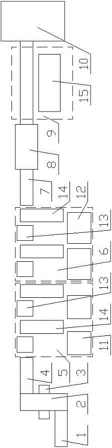
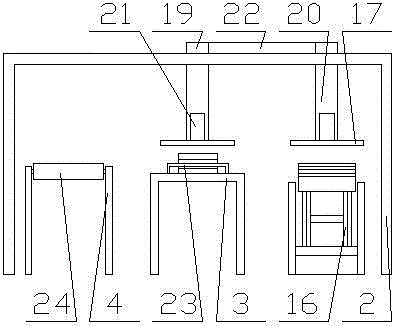
[0053] combine Figure 1~Figure 6 As shown, the present invention sequentially includes a wool material feeding device 1, a feeding transfer frame 2, a punching device 3, a bending device, a riveting device 8, an upper rib area 9 and a blanking transfer frame 10, and the punching device 3 and the bending device is provided with a conveying frame A4, between the bending device and the riveting device 8 is provided with a conveying frame B7, and the loading and transferring frame 2 is arranged on the feeding device 1, punching device 3 and Above the conveying frame A4, the conveying frame B7 is connected with the unloading and moving carrier 10 through the riveting device 8 and the ribbing device 9; the riveting device 8 is arranged on the conveying frame B7.

[0054] The feeding device 1 includes a lifting platform 16 , and the lifting platform 16 is located below the loading and transferring frame 2 .

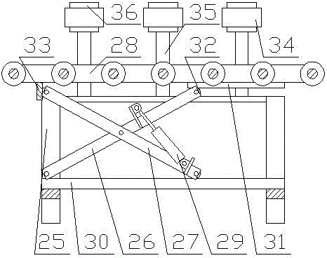
[0055] The lifting platform 16 includes a frame A25, and the top of the f...


PUM


Abstract

The invention discloses an elevator door plate production line. The elevator door plate production line sequentially comprises a blank feeding device, a feeding transfer rack, a punching device, a bending device, a riveting device, a rib applying area and a blanking transfer rack. A conveying rack A is disposed between the punching device and the bending device. A conveying rack B is mounted between the bending device and the riveting device. The feeding transfer rack is disposed above the feeding device, the punching device and the conveying rack A. The conveying rack B is connected with the blanking transfer rack through the riveting device and the rib applying area. According to the structure of the elevator door plate production line, automatic production of elevator door plates is achieved, the production efficiency of the elevator door plates is improved, and the labor cost is effectively reduced.

Description

technical field [0001] The invention relates to the field of elevator door panel processing, in particular to an elevator door panel production line. Background technique [0002] With the rise of land costs, high-rise buildings have gradually become the mainstream of the market. The higher the floor, the more elevator floors, and the demand for elevator door panels increases accordingly. [0003] With the development of modern industrial automation, higher requirements are put forward for the processing accuracy and efficiency of door panels and wall panels in the elevator field. At present, the production line of elevator door panels includes punching machines, bending machines and their loading and unloading devices. It has not yet been automated and integrated into the entire production line. Therefore, the movements of elevator door panels and wall panels are not coherent during the production process, and many processes require manual operations, which restricts the fu...

Claims


Application Information

Patent Timeline
Patent Type & Authority Applications(China)
IPC IPC(8): B21D43/18B21D43/02B21D43/00B21D45/00B23P23/06
CPCB21D43/003B21D43/02B21D43/18B21D45/00B23P23/06
Inventor 王金东
Owner JIANGYIN FIVE STAR WELDING COPPER
Why Eureka
Try Eureka