Supercharge Your Innovation With Domain-Expert AI Agents!

Material distribution system of deep dewatering machine for sludge

A deep dewatering and distribution system technology, applied in water/sludge/sewage treatment, sludge treatment, water/sewage treatment, etc., can solve the problems of uneven distribution, unstable sludge dewatering effect, vibration, etc., to ensure The effect of stable operation, stable and reliable processing capacity, and prolonged service life

Inactive Publication Date: 2016-07-06
SOUTH CHINA UNIV OF TECH
View PDF9 Cites 1 Cited by
  • Summary
  • Abstract
  • Description
  • Claims
  • Application Information

AI Technical Summary

Problems solved by technology

Therefore, it is of great significance to research and develop the sludge deep dewatering machine that mainly reduces the moisture content of the sludge from 80% to 50-60% through mechanical dehydration; a large number of systematic experimental results show that the depth of the sludge deep dewatering machine The effect of dehydration is not only related to the dehydration pressure, dehydration time, and whether the dehydration channel is smooth enough, but also has a very important relationship with the way of feeding and distributing sludge; the previous method of feeding and distributing sludge is: sludge is conveyed through a screw The machine transports it to the filter screen, and then adds a stretching roller to push the two ends of the web banner; this kind of cloth distribution method is too simple, and the change of sludge type, sludge particle size, and sludge moisture content cannot be changed accordingly; sludge The treatment capacity is unstable, and the sludge dewatering effect is also very unstable. Sometimes, the machine may vibrate due to uneven distribution.

Method used


Image

  • Material distribution system of deep dewatering machine for sludge
  • Material distribution system of deep dewatering machine for sludge
  • Material distribution system of deep dewatering machine for sludge

Examples


Embodiment Construction

[0020] The purpose of the present invention will be further described in detail through specific examples below, and the examples cannot be repeated here one by one, but the implementation of the present invention is not therefore limited to the following examples.

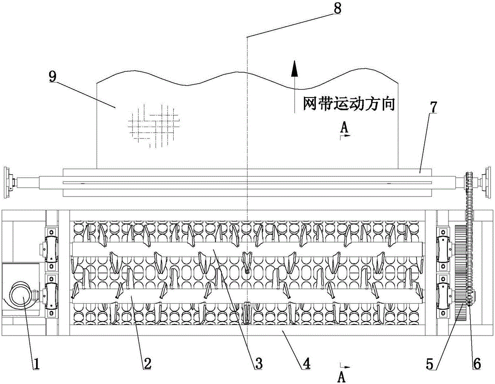
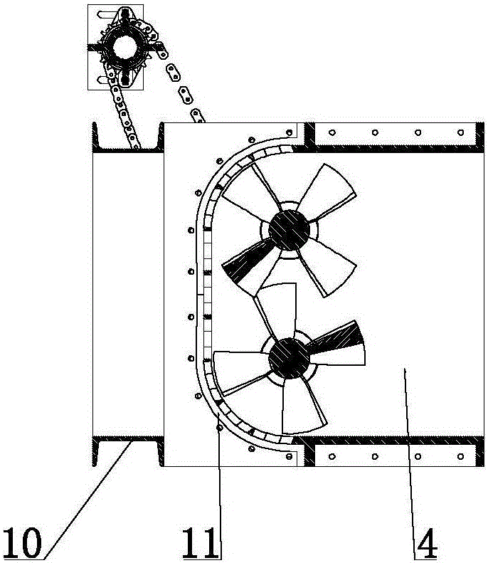
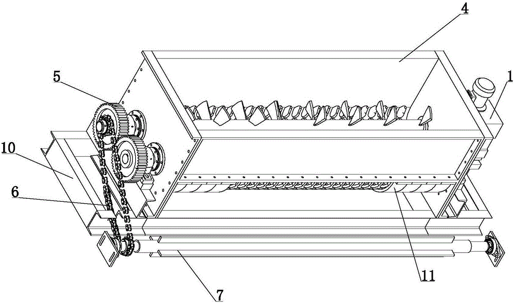
[0021] Such as Figure 1 to Figure 6 As shown, a distributing system of a deep sludge dewatering machine includes a base 10 and a hopper 4 fixedly arranged on the base 10, and the active screw with the same length of the helical part and the opposite direction is installed in the hopper 4 in parallel rotation. 2 and the driven screw 3, the two ends of the driving screw 2 and the driven screw 3 are rotatably supported by the side plates and bearings of the hopper 4, and the side plates are fixed on the mounting screw holes 16 of the hopper side plates at both ends of the hopper 4 by screws , the helical direction on the driving screw 2 and the driven screw 3 is reversely set with the centerline 8 as the line of sym...


PUM


Abstract

The invention discloses a material distribution system of a deep dewatering machine for sludge.The material distribution system comprises a base and a hopper fixedly arranged on the base, the hopper is internally provided with a drive screw rod and a driven screw rod in parallel, wherein the spiral parts of the drive screw rod and the driven screw rod are equal in length and contrary in direction, the spiral direction of the drive screw rod and the spiral direction of the driven screw rod are arranged to be contrary to each other with the center line as the symmetrical line, one end of the drive screw rod is in drive connection with a variable frequency motor arranged on one side of the hopper, and the other end of the drive screw rod is in drive connection with one end of the driven screw rod through a gear pair located on the opposite side of the hopper; the bottom of the hopper is evenly provided with material distribution holes, and filter cloth for conveying sludge is arranged under the material distribution holes.The material distribution system meets the material distribution requirements under complex situations such as changes of sludge varieties, changes of sludge particle size and changes of sludge moisture content, the treatment quantity is stable and reliable, and quite important significance is achieved for maintaining an ideal dewatering effect, guaranteeing stable operation of equipment and prolonging the service life of equipment.

Description

technical field [0001] The invention relates to sludge dewatering equipment, in particular to a material distribution system for a deep sludge dewatering machine. Background technique [0002] With the development of social economy and the acceleration of urbanization, urban sludge and industrial sludge have increased sharply. The previous treatment plan for sludge with a high moisture content of 80% has been replaced by a more scientific sludge with a low moisture content of <50-60%. Treatment options are superseded. Therefore, it is of great significance to research and develop the sludge deep dewatering machine that mainly reduces the moisture content of the sludge from 80% to 50-60% through mechanical dehydration; a large number of systematic experimental results show that the depth of the sludge deep dewatering machine The effect of dehydration is not only related to the dehydration pressure, dehydration time, and whether the dehydration channel is smooth enough, bu...

Claims


Application Information

Patent Timeline
Patent Type & Authority Applications(China)
IPC IPC(8): C02F11/12
CPCC02F11/121C02F2201/002
Inventor 黄运贤李友明
Owner SOUTH CHINA UNIV OF TECH
Features
  • R&D
  • Intellectual Property
  • Life Sciences
  • Materials
  • Tech Scout
  • Unparalleled Data Quality
  • Higher Quality Content
  • 60% Fewer Hallucinations
Learn More