A material clip conveying mechanism and electroplating equipment

A conveying mechanism and material clip technology, applied in the electrolysis process, electrolysis components, etc., can solve the problems that the deformation of the two conveyor belts cannot be guaranteed to be exactly the same, and the continuous production of thin plate electroplating cannot be realized, so as to achieve the effect of ensuring continuous normal operation

Active Publication Date: 2017-12-22
KUNSHAN DONGWEI MACHINERY CO LTD
View PDF8 Cites 0 Cited by
  • Summary
  • Abstract
  • Description
  • Claims
  • Application Information

AI Technical Summary

Problems solved by technology

[0008] Therefore, the technical problem to be solved by the present invention is that the existing clamp conveying mechanism cannot guarantee the same deformation of the two conveying belts, and cannot realize the continuous production of thin plate electroplating

Method used


Image

  • A material clip conveying mechanism and electroplating equipment
  • A material clip conveying mechanism and electroplating equipment
  • A material clip conveying mechanism and electroplating equipment

Examples


Embodiment 1

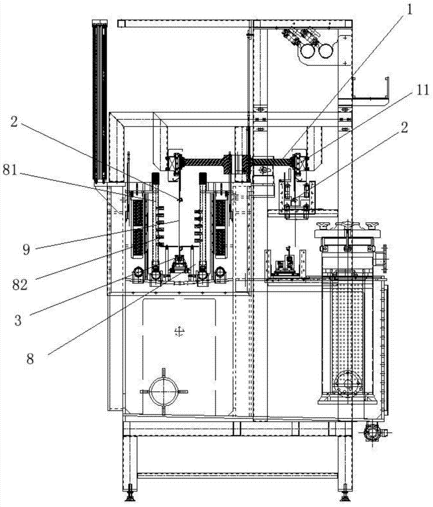
[0063] The present embodiment provides a kind of feed clip conveying mechanism, such as figure 1 shown, including,

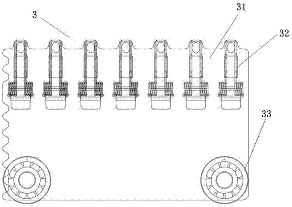
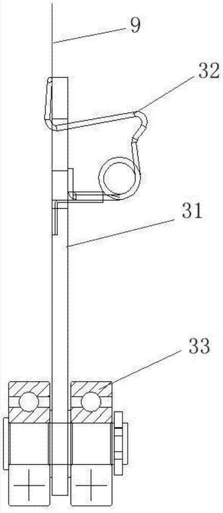
[0064] The circular track 4 is provided with a material clip 3 inside;

[0065] at least two transmission wheels 51;

[0066] The material clip transmission belt 53 is driven by the transmission wheel 51 and circulates; wherein

[0067] The clip conveying belt 53 includes a first part 53a located at the bottom or below the circular track 4 and a second part 53b away from the circular track 4, and the circular track 4 has a loop set corresponding to the first part 53a. The position part 4b and the electroplating part 4a away from the second part 53b, the clip can be driven by the first part 53a of the clip conveyor belt 53 in the return position of the circular track 4 Movement within section 4b.

[0068] The above-mentioned material clip conveying mechanism, the circular track 4 is used to limit the movement track of the material clip, and the material clip ...

Embodiment 2

[0101] A kind of electroplating equipment, such as figure 1 shown, including,

[0102] Feeding device, used to load the plates to be electroplated;

[0103] The unloading device is used to unload the plates that have been electroplated;

[0104] The electroplating tank 8 is located between the feeding device and the unloading device, and is used to form an electroplating layer on the plate to be electroplated when the plate to be electroplated passes through;

[0105] The clamp transmission belt 11 is located above the electroplating tank 8 and drives the clamps to circulate; and,

[0106] In the clip conveying mechanism described in Embodiment 1, the circular track 4 is arranged below the clamp conveyor belt 11, and the electroplating part of the circular track 4 is perpendicular to the plane where the clamp conveyor belt 11 is located. The projection coincides with the clamp transfer belt 11, the electroplating part 4a of the circular track 4 passes through the electropla...


PUM

PropertyMeasurementUnit
thicknessaaaaaaaaaa

Abstract

The invention relates to a feed collet conveying mechanism and electroplating equipment. An annular track is used for limiting movement tracks of feed collets; the feed collets move, circulating in the annular track, clamp plates to be electroplated from the lower ends to carry out electroplating when entering an electroplating part and reenter the electroplating part through a return part after electroplating is finished; and driving wheels and a transmission belt are only used for driving the feed collets to move in the return part of the annular track, and thus the feed collets run in a circulating manner. According to the feed collet conveying mechanism and the electroplating equipment, when the transmission belt is at the electroplating part, also namely, the feed collets are not driven by the transmission belt when running in the section of a feeding device, an electroplating groove and a blanking device, the feed collets are driven by a clamp conveyor belt at the upper part and the plates to be electroplated, which are clamped together; and when the clamp and the feed collets clamp the plates to be electroplated, a power source is only from the clamp conveyor belt at the upper end, so that the clamp and the feed collets are correspondingly arranged in the vertical direction to make the feeding position remain unchanged, ensure the feeding device to continuously and normally run and ensure the perpendicularity of the plates to be electroplated.

Description

technical field [0001] The invention relates to the field of circuit board electroplating technical equipment, in particular to a clip conveying mechanism and electroplating equipment. Background technique [0002] During the electroplating process, it is often necessary to electroplate circuit boards of different thicknesses. Before electroplating, the circuit boards of different thicknesses need to be clamped by clamps to maintain the verticality of the circuit boards in the electroplating bath, thereby ensuring the quality of electroplating. [0003] For a circuit board with a large thickness, due to the high strength of the circuit board itself, it is only necessary to clamp the upper edge of the circuit board through the clamp located above the circuit board during the clamping process. Gravity allows the board to maintain a good verticality. At present, the clamping of thicker circuit boards has been fully automated. For example, the Chinese patent document CN20249260...

Claims


Application Information

Patent Timeline
Patent Type & Authority Patents(China)
IPC IPC(8): C25D17/08C25D17/00
CPCC25D17/00C25D17/08
Inventor 江泽军刘涛吴志鹏程堂元阮向
Owner KUNSHAN DONGWEI MACHINERY CO LTD
Why Eureka
Try Eureka