Cleaning device and method for cleaning industrially manufactured components

A cleaning equipment, industrial manufacturing technology, applied in the direction of cleaning method using liquid, cleaning method using gas flow, cleaning method and utensils, etc., can solve the problems of less laundry replacement, washing clothes without consideration, unimportant, etc. To achieve the effect of improved heat absorption capacity, small loss, and increased temperature difference

Inactive Publication Date: 2015-09-30
TMS TURNKEY MFG SOLUTIONS
View PDF12 Cites 0 Cited by
  • Summary
  • Abstract
  • Description
  • Claims
  • Application Information

AI Technical Summary

Problems solved by technology

But the laundry process is a longer process and fewer laundry changes occur, so that the laundry change process can be ignored in the total resource consideration
Furthermore, all the solvent and thus the heat contained therein has already been extracted when the laundry is changed, so that the laundry change is insignificant from the point of view of resource loss

Method used


Image

  • Cleaning device and method for cleaning industrially manufactured components
  • Cleaning device and method for cleaning industrially manufactured components

Examples


Embodiment Construction

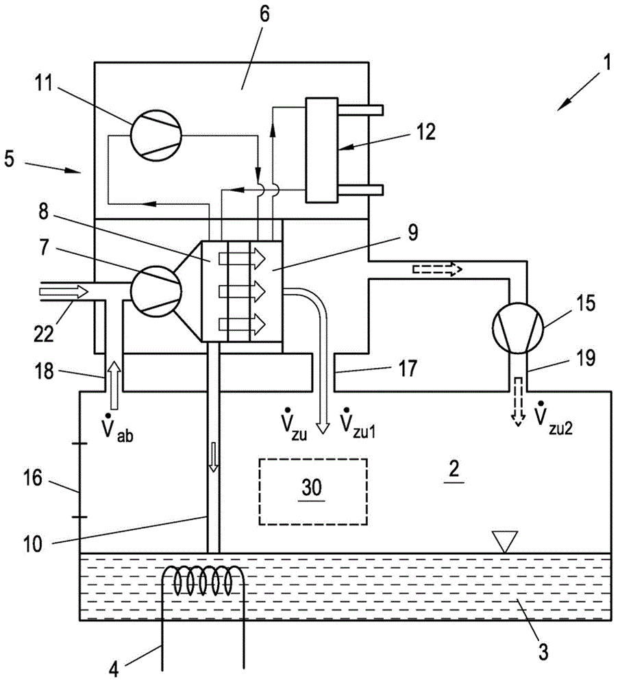
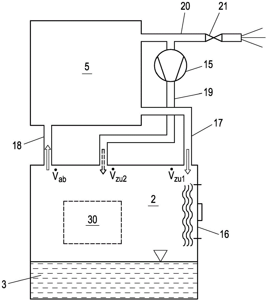
[0020] According to the cleaning device 1 of the present invention, such as figure 1 and figure 2 Schematically described, including a clean room 2, a cleaning agent container 3 and a recovery device 5, in which a component 30 is arranged during operation, such as figure 1 shown. The cleaning agent in the cleaning agent container 3 is kept at a defined operating temperature, for example 65° C. Also can be provided with detergent heating device 4 in detergent container 3 li for this, as figure 1 indicated, e.g. in order to bring the cleaning agent to or maintain the operating temperature. As cleaning agents, for example, water and chemical cleaning agents can be used. The manner in which the component 30 is cleaned in the clean room 2 is not decisive for the invention. For example, spray nozzles can be provided in the cleaning chamber 2, or robot-controlled nozzles or robot-controlled components 30 can be used. As a result of the cleaning process, a cleaning agent mist, ...


PUM


Abstract

In order to recover the resources (cleaning agent, heat) contained in the cleaning agent vapors suctioned off a cleaning system for cleaning industrially produced components, it is proposed to guide the suctioned-off waste air ({dot over (V)}ab) in a recovery device (5) through a heat register (9) of a refrigeration device (6) and thereby to heat it substantially to the temperature of the waste air ({dot over (V)}ab), and to supply the waste air ({dot over (V)}ab) heated and dried in this manner to the cleaning chamber (2) in the region of a bulkhead door (16) as preheated dried supply air ({dot over (V)}zu).

Description

technical field [0001] The invention relates to a cleaning device and a method for cleaning industrially manufactured components. Background technique [0002] Cleaning plants for cleaning industrially produced components, such as machined components, require a large amount of resources, such as water, cleaning agents and energy, during operation. The reason for this loss is primarily that the components have to be cleaned with hot cleaning agent, so that cleaning agent mist (saturated steam) is generated in the cleaning device, which until now was simply sucked out of the device and released into the environment. Thus, on the one hand water, cleaning agent and, on the other hand, the thermal energy contained in the discharged cleaning agent mist are lost. For a typical cleaning solution with a filling capacity of 2000l, a cleaning temperature of 600°C and an exhaust capacity of 4500m 3 And calculations for a cleaning plant with a heating power of 110kW give a heat loss of...

Claims


Application Information

Patent Timeline
Patent Type & Authority Patents(China)
IPC IPC(8): B08B15/02B08B3/02B01D53/00F28D21/00B01D53/26
CPCB08B5/04B01D2258/02B01D53/002F28D21/0014B01D2258/06B08B3/02B01D53/265B01D2257/80B01D53/38B08B15/02
Inventor R·维腾多尔夫
Owner TMS TURNKEY MFG SOLUTIONS
Why Eureka
Try Eureka