Fluid director using exhaust leaving velocity loss of steam turbine

A residual speed loss, steam turbine technology, applied in the direction of machines/engines, components of pumping devices for elastic fluids, mechanical equipment, etc., can solve the problems of increasing the length of the main shaft of the steam turbine, affecting the efficiency of the low-pressure cylinder, and lack of feasibility. , to achieve the effect of reduced heat consumption rate, significant energy saving benefits, and easy implementation

Active Publication Date: 2016-07-06
XI AN JIAOTONG UNIV
View PDF4 Cites 3 Cited by
  • Summary
  • Abstract
  • Description
  • Claims
  • Application Information

AI Technical Summary

Problems solved by technology

[0002] Residual velocity loss is the main energy loss of steam turbines, especially the low-pressure cylinder of modern large-scale steam turbines. Since the steam flow velocity away from the last stage moving blade is as high as hundreds of meters, the residual velocity loss is as high as 20kJ / kg or more, which greatly affects the relative internal pressure of the low-pressure cylinder. efficiency
Although the traditional diffuser channel can utilize the kinetic energy of high-speed steam, it needs a very long channel to achieve the effect due to its small expansion angle, which greatly increases the length of the main shaft of the steam turbine and is not feasible.

Method used


Image

  • Fluid director using exhaust leaving velocity loss of steam turbine
  • Fluid director using exhaust leaving velocity loss of steam turbine
  • Fluid director using exhaust leaving velocity loss of steam turbine

Examples


Embodiment Construction

[0014] In order to make the purpose, technical solution and advantages of the present invention more clear and concise, the present invention will be further described in detail below in conjunction with the accompanying drawings and embodiments. It should be understood that the specific embodiments described here are only used to explain the present invention, not to limit the present invention.

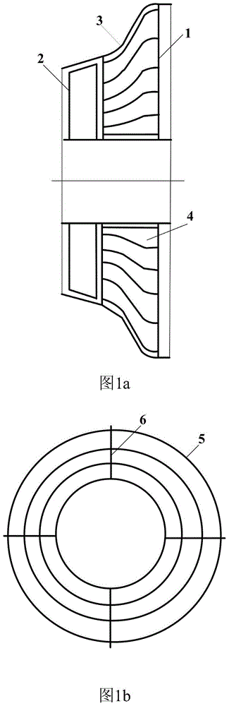
[0015] Such as figure 1 middle figure 1 a and figure 1 As shown in b, the present invention is a deflector utilizing steam turbine exhaust after-velocity loss. The deflector 1 is arranged downstream of the last-stage moving blade 2 of the steam turbine and fixed on the cylinder 3 of the steam turbine. The deflector 1 It consists of a plurality of S-shaped annular deflectors 5 socketed. Adjacent annular deflectors 5 are fixed radially by multiple fixers 6 with streamlined cross-sections. Adjacent annular deflectors 5 forms diversion passage 4; The direction of the entrance of said...


PUM


Abstract

The invention discloses a fluid director using exhaust leaving velocity loss of a steam turbine. The fluid director is arranged at the downstream of a final moving blade of the steam turbine, is fixed on a cylinder of the steam turbine, and is formed by sleeving multiple annular fluid directing pieces with S-shaped sections; the adjacent annular fluid directing pieces are fixed in the radial direction through multiple fixators with streamlined sections; fluid directing channels are formed between the adjacent annular fluid directing pieces; the direction of inlets of the fluid directing channels is the same with the direction of steam current velocity behind the final blade of the steam turbine; the direction of outlets of the fluid directing channels is the horizontal direction; the fluid directing channels adopt gradually increased channels from the inlets to the outlets; and a ratio of the sectional area sum of the outlets of the fluid directing channels to the sectional area sum of the inlets of the fluid directing channels is 1.5-2. The fluid director can obtain a prominent pressure increasing effect in shorter channels to effectively use the leaving velocity loss of the steam turbine. Indicated through calculation, for a modern large thermal power generating unit, the technology can obviously reduce the heat rate of a turbogenerator under the precondition of not largely increasing the unit investment, and has prominent energy saving benefit.

Description

technical field [0001] The invention belongs to the technical field of utilizing the residual velocity loss of exhaust steam of a steam turbine, and in particular relates to a deflector for utilizing the residual velocity loss of exhaust steam of a steam turbine. Background technique [0002] Residual velocity loss is the main energy loss of steam turbines, especially the low-pressure cylinder of modern large-scale steam turbines. Since the steam flow velocity away from the last stage moving blade is as high as hundreds of meters, the residual velocity loss is as high as 20kJ / kg or more, which greatly affects the relative internal pressure of the low-pressure cylinder. efficiency. Although the traditional diffuser channel can utilize the kinetic energy of high-speed steam, it needs a very long channel to achieve the effect due to its small expansion angle, which greatly increases the length of the main shaft of the steam turbine and is not feasible. Contents of the inventi...

Claims


Application Information

Patent Timeline
IPC IPC(8): F01D25/30F04D29/54B05B15/00
CPCF01D25/30F04D29/542B05B15/00
Inventor 刘继平邢秦安严俊杰种道彤王进仕刘明
Owner XI AN JIAOTONG UNIV
Why Eureka
Try Eureka