
Common Rail Diesel Engine Fuel Injection Control System

A control system and diesel engine technology, applied in engine control, fuel injection control, electrical control, etc., can solve the problems of complex control logic of the main control chip, lack of perfect fault diagnosis strategy, failure to realize fault type judgment, etc., to achieve fault diagnosis and The effect of perfect hardware protection strategy

Active Publication Date: 2018-06-19
LIANCHUANG AUTOMOBILE ELECTRONICS
View PDF6 Cites 0 Cited by
  • Summary
  • Abstract
  • Description
  • Claims
  • Application Information

AI Technical Summary

Problems solved by technology

This scheme uses discrete components to design the fuel injection drive control and protection circuit of the engine electronic control unit (ECU), which can realize the control of the fuel injection drive voltage above 60V, but its disadvantage is that a large number of discrete components make the engine electronic control unit (ECU) low circuit integration and high cost; the control logic of the main control chip (MCU) is complex; although the engine electronic control unit (ECU) can realize the fault protection of the fuel injector hardware, it does not have a complete fault diagnosis strategy and cannot realize specific fault types judge

Method used


Image

  • Common Rail Diesel Engine Fuel Injection Control System
  • Common Rail Diesel Engine Fuel Injection Control System
  • Common Rail Diesel Engine Fuel Injection Control System

Examples


Embodiment 1

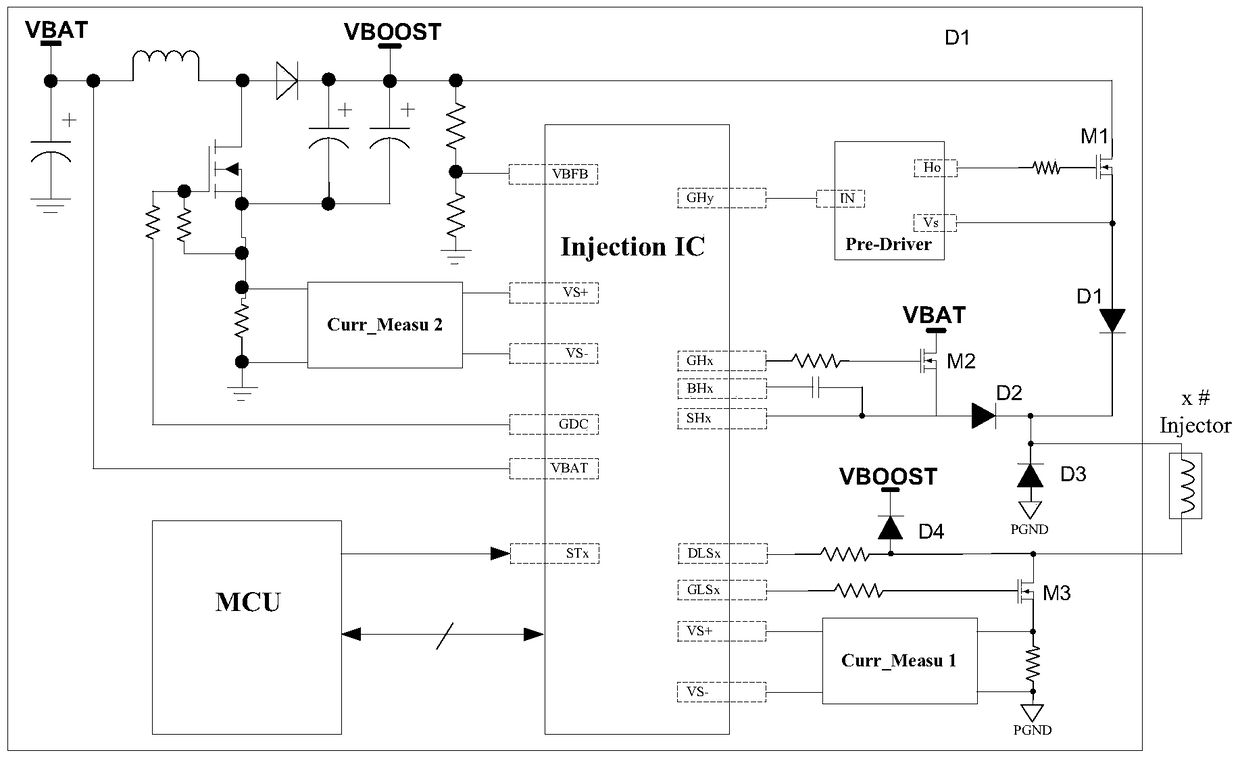
[0048] Common rail diesel fuel injection control system, such as figure 1 As shown, including boost circuit module (BOOST DC_DC), fuel injection control module (Injection IC), pre-driver module (Pre_Driver IC), main processor (MCU);

[0049] The main processor (MCU) judges the current injection task, and sends the cylinder sequence signal STx to the fuel injection control module (Injection IC);

[0050] The step-up circuit module is used for DC voltage conversion, and boosts the battery voltage VBAT to fuel injection drive high voltage VBOOST;

[0051] The fuel injector (x#Injector) of the X cylinder, the high side is connected to the lower end of the first power switch tube M1 and the lower end of the second power switch tube M2, and the low side is connected to the upper end of the third power switch tube M3; the X cylinder Any cylinder of a diesel engine;

[0052] The first power switch tube M1 is connected to the fuel injection drive high voltage VBOOST at the upper end;...

Embodiment 2

[0072] Based on the common-rail diesel engine fuel injection control system of Embodiment 1, the common-rail diesel engine fuel injection control system further includes a first current sampling module Curr_mesau1 and a second current sampling module Curr_mesau2;

[0073] The first current sampling module Curr_mesau1 is used to detect the current Curr1 between the lower end of the third power switch tube M3 and the ground;

[0074] The second current sampling module Curr_mesau2 is used to detect the current Curr2 at the upper end of the first power switch tube M1.

[0075] The first current sampling module Curr_mesau1 and the second current sampling module Curr_mesau2 can be integrated in the fuel injection control module (Injection IC), or can be realized through an external operational amplifier circuit.

[0076] Such as figure 2 As shown, the main injection current waveform of the injector of cylinder X consists of the opening acceleration phase Peak, the transitional shu...

Embodiment 3

[0090] Based on the common rail diesel engine fuel injection control system of Embodiment 2, the fuel injection control module, according to the voltage Vds_hs between the upper and lower ends of the second power switch tube M2, and the voltage Vsrc_hs between the lower end of the second power switch tube M2 and the ground , the voltage Vds_ls between the upper end of the third power switch tube M3 and the ground, the current Curr1 between the lower end of the third power switch tube M3 and the ground detected by the first current sampling module Curr_mesau1, and the first power detected by the second current sampling module Curr_mesau2 The current Curr2 at the upper end of the switch tube M1 is used for fault diagnosis.

[0091] Taking the fuel injector fault diagnosis of cylinder x as an example, the truth tables of basic fault diagnosis and hardware protection strategies are shown in Table 1 to Table 4. Vds_hs is the voltage between the upper and lower ends of the second po...


PUM


Abstract

The invention discloses a fuel injection control system for a common rail diesel engine. The high-side high-voltage control signal output by the fuel injection control module is sent to a pre-drive module, and the pre-drive module outputs an enhanced high-side high-voltage control signal to control the first power switch tube. The on-off of the fuel injector is realized to turn on or off the fuel injection driving high pressure, because the driving power of the output port of the enhanced high-side high-voltage control signal of the pre-drive module is higher than that of the high-side high-voltage control of the fuel injection control module The driving power of the signal output port, so the fuel injection control with higher fuel injection driving voltage requirements can be realized. The common rail diesel engine fuel injection control system of the present invention can realize fuel injection control with high fuel injection driving voltage, and has perfect fault diagnosis and hardware protection strategies, which not only simplifies the control circuit of discrete device scheme design, has clear topology structure, and greatly reduces costs , It also solves the difficulties in the fault diagnosis and hardware protection strategy implementation of the discrete device control mode.

Description

technical field [0001] The invention relates to engine control technology, in particular to a fuel injection control system for a common rail diesel engine. Background technique [0002] With the in-depth control of air pollution and the increasingly stringent automobile emission regulations, on the basis of traditional high-pressure common rail technology, the drive voltage of the injector of the engine electronic control unit (ECU) is further increased and the precise control and control of multiple fuel injections are realized. A complete fault diagnosis strategy has become one of the mainstream technical solutions for diesel engines to meet higher emission regulations. [0003] At present, the traditional common rail diesel engine fuel injection control technologies mainly include: [0004] 1) The application-specific integrated circuit (IC) solution realizes the fuel injection control of the common rail diesel engine. When this scheme is controlled, although the circu...

Claims


Application Information

Patent Timeline
Patent Type & Authority Patents(China)
IPC IPC(8): F02D41/30
Inventor 阙发松
Owner LIANCHUANG AUTOMOBILE ELECTRONICS
Learn More