Hydroelectric generator

A technology for hydroelectric generators and generators, used in hydroelectric power generation, engine components, machines/engines, etc., can solve problems such as maintenance and maintenance difficulties, waste of resources, single function, etc., to achieve simple design, improve efficiency, and increase power generation. Effect

Inactive Publication Date: 2016-07-06
彭伟成
View PDF8 Cites 5 Cited by
  • Summary
  • Abstract
  • Description
  • Claims
  • Application Information

AI Technical Summary

Problems solved by technology

Although the utilization of water energy is relatively mature at present, for many remote places, such as deep mountainous areas, there will not be a large amount of hydropower resources, and generally there is no need for large-power hydroelectric generators. At the same time, hydropower currently on the market There are problems such as single function, serious waste of resources, difficulty in maintenance and maintenance, and high cost.

Method used


Image

  • Hydroelectric generator
  • Hydroelectric generator

Examples


Embodiment 1

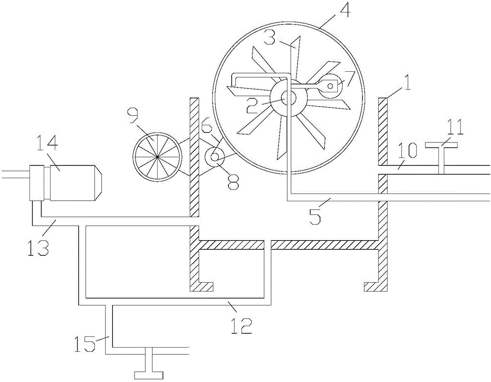
[0022] refer to figure 1 As shown, a hydroelectric generator includes an organic base 1, a rotating shaft 2 and a runner 4, the base 1, the rotating shaft 2 and the runner 4 are connected in sequence, and the rotating shaft 2 is provided with more than one paddle 3, The machine base 1 is set in a concave shape, the machine base 1 is provided with a penetrating water inlet pipe 5, the water inlet pipe 5 is provided with a high-pressure water pump 7, and the machine base 1 is connected with a first suction pipe 10 , shunt pipe 12 and outlet pipe 13, described shunt pipe 12 communicates with outlet pipe 13, is connected with second suction pipe 15 on the described shunt pipe 12, and described first suction pipe 10 and second suction pipe 15 Valves 11 are arranged on each of them, a water pump 14 is arranged on the outlet pipe 13, a generator 9 is arranged outside the base 1, a pulley 8 is arranged between the generator 9 and the runner 4, and the generator 9 and runner 4 all ado...

Embodiment 2

[0036] refer to figure 1 As shown, a hydroelectric generator includes an organic base 1, a rotating shaft 2 and a runner 4, the base 1, the rotating shaft 2 and the runner 4 are connected in sequence, and the rotating shaft 2 is provided with more than one paddle 3, The machine base 1 is set in a concave shape, the machine base 1 is provided with a penetrating water inlet pipe 5, the water inlet pipe 5 is provided with a high-pressure water pump 7, and the machine base 1 is connected with a first suction pipe 10 , shunt pipe 12 and outlet pipe 13, described shunt pipe 12 communicates with outlet pipe 13, is connected with second suction pipe 15 on the described shunt pipe 12, and described first suction pipe 10 and second suction pipe 15 Valves 11 are arranged on each of them, a water pump 14 is arranged on the outlet pipe 13, a generator 9 is arranged outside the base 1, a pulley 8 is arranged between the generator 9 and the runner 4, and the generator 9 and runner 4 all ado...

Embodiment 3

[0050] refer to figure 1 As shown, a hydroelectric generator includes an organic base 1, a rotating shaft 2 and a runner 4, the base 1, the rotating shaft 2 and the runner 4 are connected in sequence, and the rotating shaft 2 is provided with more than one paddle 3, The machine base 1 is set in a concave shape, the machine base 1 is provided with a penetrating water inlet pipe 5, the water inlet pipe 5 is provided with a high-pressure water pump 7, and the machine base 1 is connected with a first suction pipe 10 , shunt pipe 12 and outlet pipe 13, described shunt pipe 12 communicates with outlet pipe 13, is connected with second suction pipe 15 on the described shunt pipe 12, and described first suction pipe 10 and second suction pipe 15 Valves 11 are arranged on each of them, a water pump 14 is arranged on the outlet pipe 13, a generator 9 is arranged outside the base 1, a pulley 8 is arranged between the generator 9 and the runner 4, and the generator 9 and runner 4 all ado...


PUM


Abstract

The invention discloses a hydroelectric generator. The hydroelectric generator comprises a seat, a rotary shaft and a rotary wheel, wherein the seat, the rotary shaft and the rotary wheel are sequentially connected; more than one paddle is arranged on the rotary shaft; the seat is arranged in a concave shape; a penetrating water inlet tube is arranged on the seat; a high-pressure water pump is arranged on the water inlet tube; a first gas absorption tube, a flow division tube and a water outlet tube are connected to the seat; the flow division tube is communicated with the water outlet tube; a second gas absorption tube is connected to the flow division tube; a valve is arranged on each of the first gas absorption tube and the second gas absorption tube; a water pumping machine is arranged on the water outlet tube; a generator is arranged outside the seat; a belt wheel is arranged between the generator and the rotary wheel; and the generator and the rotary wheel are both connected with the belt wheel by virtue of a belt. The hydroelectric generator is simple in design, high in generating capacity, and high in working efficiency.

Description

technical field [0001] The invention relates to a hydroelectric generator. Background technique [0002] With the rapid development of the economy and the continuous improvement of people's living standards, people's demand for various resources and energy is also increasing. At present, coal, electricity, gas and other non-renewable resources have the highest utilization efficiency and conversion rate. Although the use of resources is relatively mature, the dwindling situation makes it impossible for people to pin all their hopes on these aspects. Therefore, with the advancement of science and technology, people began to continuously research and develop various renewable resources. Among these renewable resources, solar energy, tidal energy, and wind energy are the focus of people's research. These resources or energy are not only renewable, At the same time, it is clean and pollution-free, so it is widely concerned by scientists and researchers. [0003] People have a l...

Claims


Application Information

Patent Timeline
Patent Type & Authority Applications(China)
IPC IPC(8): F03B13/00F03B3/00F03B3/12F03B11/00C08L61/00C08L75/04C08L1/28C08K13/02C08K3/04C08K3/08C08K3/36C08K3/34B29C39/02
CPCB29C39/02C08L61/00C08L2205/03F03B3/00F03B3/121F03B11/00F03B11/002F03B13/00C08L75/04C08L1/284C08K13/02C08K3/04C08K2003/0812C08K3/36C08K3/346Y02E10/20
Inventor 彭伟成
Owner 彭伟成
Why Eureka
Try Eureka