Adjusting ball valve

A ball-regulating and flow-regulating technology, applied in valve devices, cocks including cut-off devices, engine components, etc., can solve problems such as equipment failures, strong resonance of on-site pipelines and other equipment, and hazards to the living environment of surrounding residents.

Active Publication Date: 2016-07-06
HUANQIU VALVE GROUP
View PDF9 Cites 5 Cited by
  • Summary
  • Abstract
  • Description
  • Claims
  • Application Information

AI Technical Summary

Problems solved by technology

[0013] 2. Noise
A large number of bubbles formed by flash evaporation burst one after another in a short period of time, forming a wide frequency noise, which not only affects the physical and mental health of the on-site staff, but also seriously harms the living environment of the surrounding residents;
[0014] 3. Cause strong vibration
The bursting of a large number of bubbles produces continuous high-frequency vibration, which is likely to cause strong resonance of on-site pipelines and other equipment, and even cause equipment failure in severe cases, resulting in major safety accidents

Method used


Image

  • Adjusting ball valve
  • Adjusting ball valve
  • Adjusting ball valve

Examples


Embodiment 1

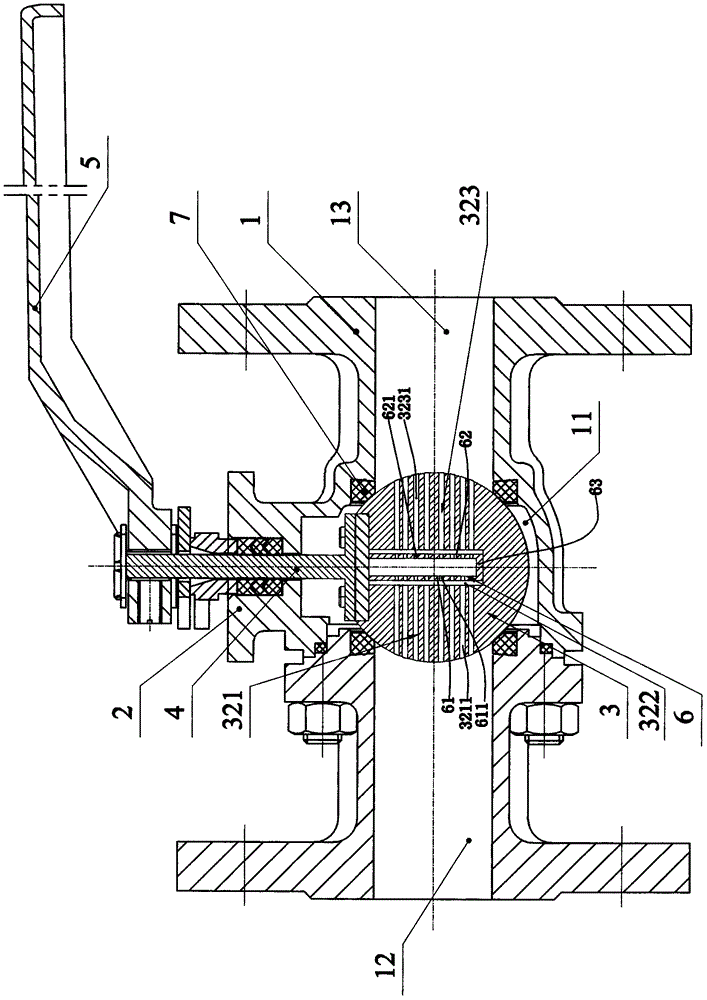
[0043] Such as Figure 1-5The specific embodiment of the present invention shown includes a valve body 1, a valve cover 2, a ball 3, a valve seat 7, a valve stem 4 and a driving mechanism 5 for driving the rotation of the valve stem. The driving mechanism described in this embodiment is a rotating handle .

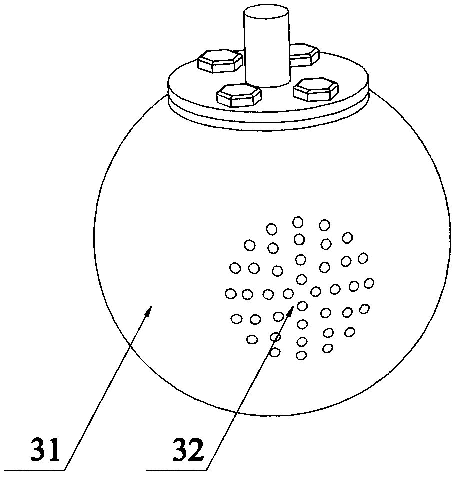
[0044] The valve body 1 is provided with a valve cavity 11 and a medium inlet 12 and a medium outlet 13 which are connected to the valve cavity 11. The ball 3 is rotatably arranged in the valve cavity 11 and connected with the valve stem 4 in linkage. The sphere 3 described above includes a closing portion 31 capable of closing the medium inlet 12 and the medium outlet 13 and a conducting portion 32 capable of conducting the medium inlet 12 and the medium outlet 13, and the conducting portion 32 includes The inlet is sequentially connected to the conduction entry part 321, the middle through groove 322 and the conduction outflow part 323 in the direction of the medium out...

Embodiment 2

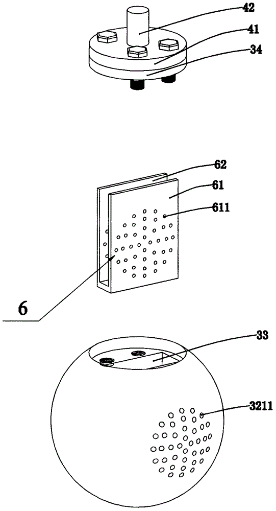
[0050] Such as Figure 6-8 As shown in the specific implementation of the present invention, the difference between this embodiment 2 and embodiment 1 is that: the middle channel 322 is a cylindrical hole, and the flow regulating inner part 6 is fixedly arranged in the cylindrical hole The cylindrical member, the flow regulating inlet hole 611 is horizontally penetratingly arranged on the side wall of the cylindrical member corresponding to the side entering the through hole 3211, and the flow regulating outlet hole 621 is horizontally penetratingly arranged on the cylindrical member corresponding to the On the side wall of the outflow through hole, the inner end of the flow adjustment inlet hole 611 and the inner end of the flow adjustment outlet hole 621 communicate with each other in the inner cavity of the cylindrical member.

Embodiment 3

[0052] Such as Figure 9-10 As shown in the specific implementation of the present invention, the difference between this embodiment and Embodiment 1 is that there is one conduction entry part 321 described in this embodiment, and two conduction outflow parts 323 are provided; the one The conduction inlet portion 321 and the two conduction outflow portions 323 are evenly distributed at 120 degrees on the circumferential surface of the sphere. In addition, the shape of the intermediate channel 322 in this embodiment is a triangular column. Correspondingly, the shape of the flow regulating inner part 6 in the middle channel 322 of this embodiment may preferably be a cylindrical structure with a triangular cross section.


PUM


Abstract

The invention discloses an adjusting ball valve which comprises a valve, a bonnet, a ball, a valve stem and a driving mechanism. The valve stem can be driven by the driving mechanism to rotate, the valve is provided with a valve cavity, a medium inlet and a medium outlet, the medium inlet and the medium outlet are communicated with the valve cavity, the ball is arranged in the valve cavity, is connected with the valve stem in a linkage manner and comprises a closing portion and a communication portion, the medium inlet and the medium outlet can be closed by the closing portion and can be communicated with each other via the communication portion, the communication portion comprises a communication inlet portion, a middle straight slot and a communication outflow portion which are sequentially communicated and connected with one another in the direction from the medium inlet to the medium outlet, the communication inlet portion is provided with a plurality of inlet through holes which are parallelly formed at intervals, the communication outflow portion is provided with a plurality of outflow through holes which are parallelly formed at intervals, and the inner ends of the inlet through holes and the inner ends of the outflow through holes are communicated with the middle straight slot. The adjusting ball valve has the advantages of reasonable structural design and accuracy in flow adjustment.

Description

technical field [0001] The invention relates to a regulating ball valve. Background technique [0002] The ball valve is a commonly used valve, and its structure generally includes a valve body, a valve cover, a ball, a valve stem, and a driving mechanism for driving the valve stem to rotate. The valve body is provided with a valve cavity and a medium inlet and medium outlet, the ball is arranged in the valve cavity and connected with the valve stem. [0003] At present, when the sphere of the traditional ball valve has a small opening, the flow rate reaches the maximum value. In other words, there is no linear relationship between the liquid flow of the ball valve and the opening of the ball, so the flow of the ball valve cannot be adjusted linearly and accurately. [0004] In addition, as known to those skilled in the art, when the liquid medium in the pipeline flows through the throttling section of the valve, the flow rate increases and the static pressure decreases. ...

Claims


Application Information

Patent Timeline
Patent Type & Authority Applications(China)
IPC IPC(8): F16K5/06F16K5/10
CPCF16K5/06F16K5/0605F16K5/10
Inventor 黄建斌
Owner HUANQIU VALVE GROUP
Why Eureka
Try Eureka