

Ball valve
A technology of ball valves and valve seats, applied in valve details, valve devices, valve operation/release devices, etc., can solve problems such as waste of water resources, water leakage, inconvenient use, etc., to prevent water leakage and prolong service life , the effect of good sealing performance
- Summary
- Abstract
- Description
- Claims
- Application Information
AI Technical Summary
Problems solved by technology
Method used
Image

Examples
Embodiment Construction
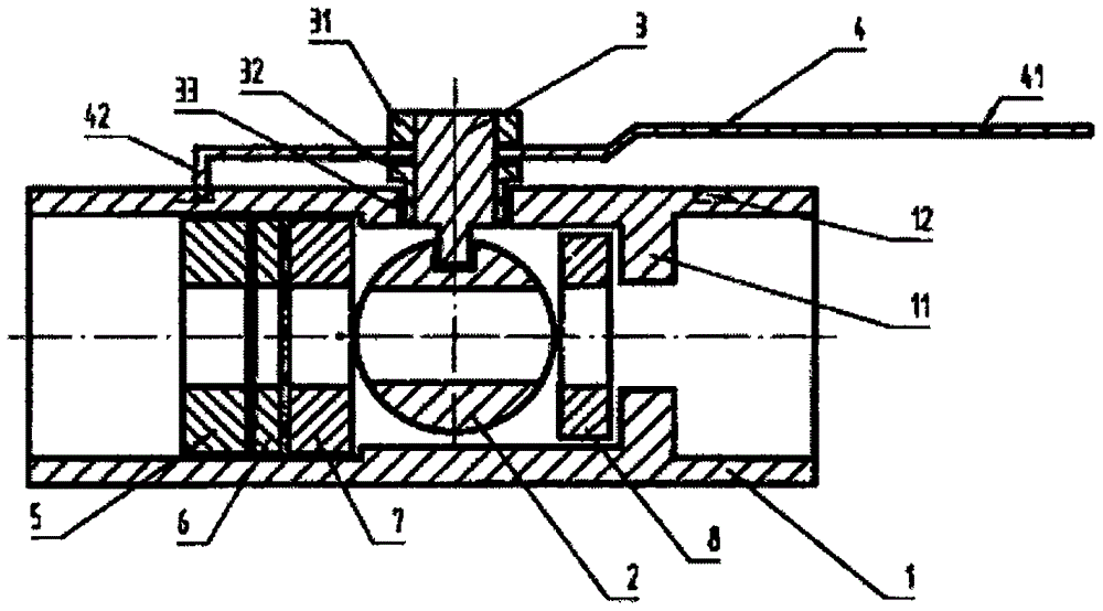
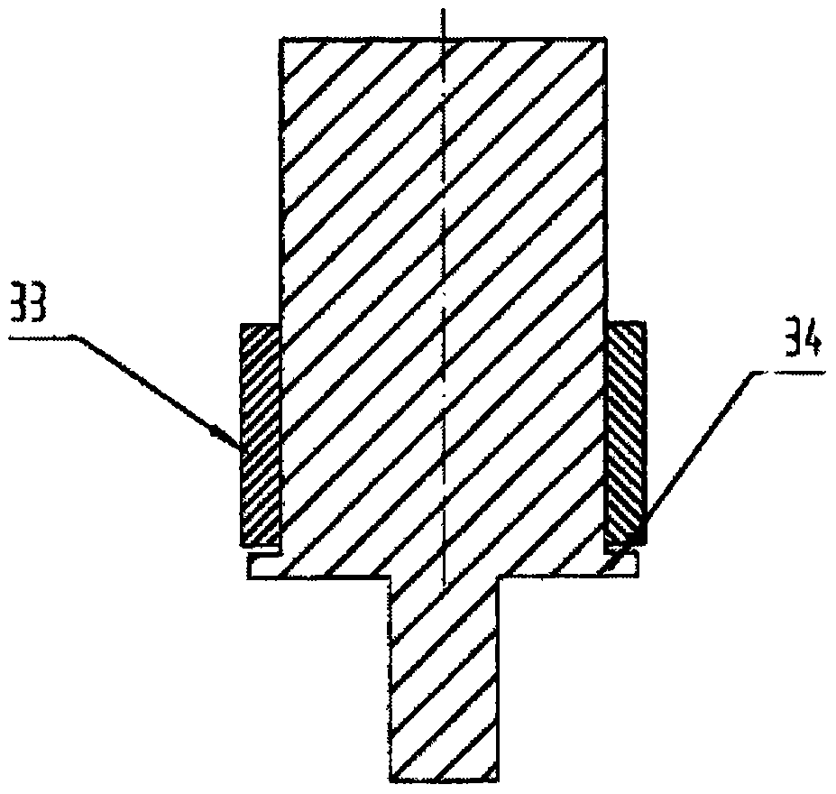
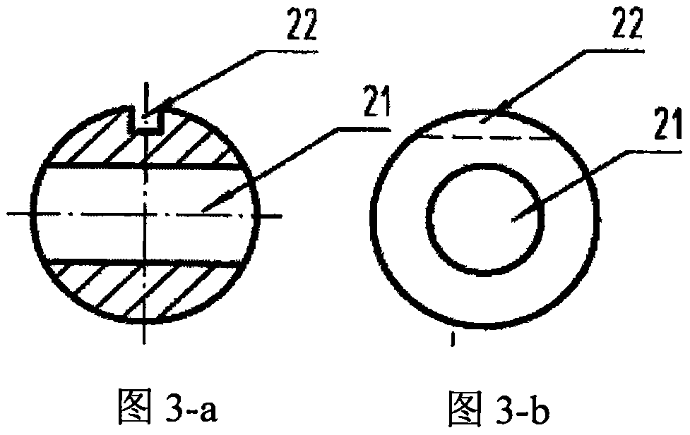
[0012] refer to Figure 1 ~ Figure 4 As can be seen, the stainless steel ball valve of the present invention is made up of valve seat 1, spool 2, pin 3, fixed nut 32, hexagonal bolt 5 and opening and closing handle 4, and valve seat 1 is a stainless steel garden tubular lumen, A garden hole is set on the central body wall, the valve core 2 is arranged in the middle of the lumen of the valve seat 1, and a wear-resistant washer 7, 8 is respectively arranged on the left and right sides, and a stainless steel washer 6 is also set between the wear-resistant washer 7 and the hexagonal bolt 5, Then use the hexagonal bolt 5 screw extrusion and the spool 11 to control the spool 2 so that the spool 2 cannot move left and right, and the groove 22 on the spool 2 is aligned with the garden hole in the valve seat 1, and then the pin The sub 3 is inserted into the groove 22 on the spool 2, and the pin 3 is controlled on the valve seat 1 with a fixed nut 32, and a wear-resistant washer 33 is ...
PUM
 Abstract
Description
Claims
Application Information