Liquid supply device

A liquid supply and liquid technology, applied in the field of the Internet of Things, can solve the problems of waste of resources, time-consuming and troublesome debugging process, and inability to know the temperature of the outlet water, etc., and achieve the effect of remote control and convenient and flexible control methods

Active Publication Date: 2016-07-06
BUBBLE LAB CO LTD
View PDF6 Cites 11 Cited by
  • Summary
  • Abstract
  • Description
  • Claims
  • Application Information

AI Technical Summary

Problems solved by technology

After this kind of hot and cold water faucet is turned on, people can't know the temperature of the water outlet, they can only test it by hand, and it takes many times of debugging to reach the temperature people need.
The debugging process is time-consuming and troublesome, and the water is too hot to cause burns
In addition, this kind of faucet cannot quantitatively discharge water, which is easy to cause waste of resources
[0004] At present, there are also electronically controlled faucets, such as faucets integrated with infrared sensors. This type of faucet has a single function and can only automatically control the water on and off, which affects the promotion of technology.

Method used


Image

  • Liquid supply device
  • Liquid supply device
  • Liquid supply device

Examples


Embodiment 1

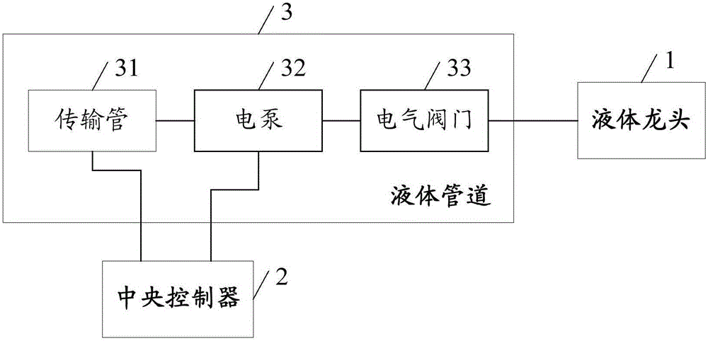
[0045] figure 1 The structural block diagram of the liquid supply equipment provided for this embodiment, such as figure 1 As shown, the liquid supply equipment includes: a liquid faucet 1, a central controller 2 and a liquid pipeline 3;

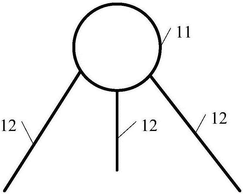
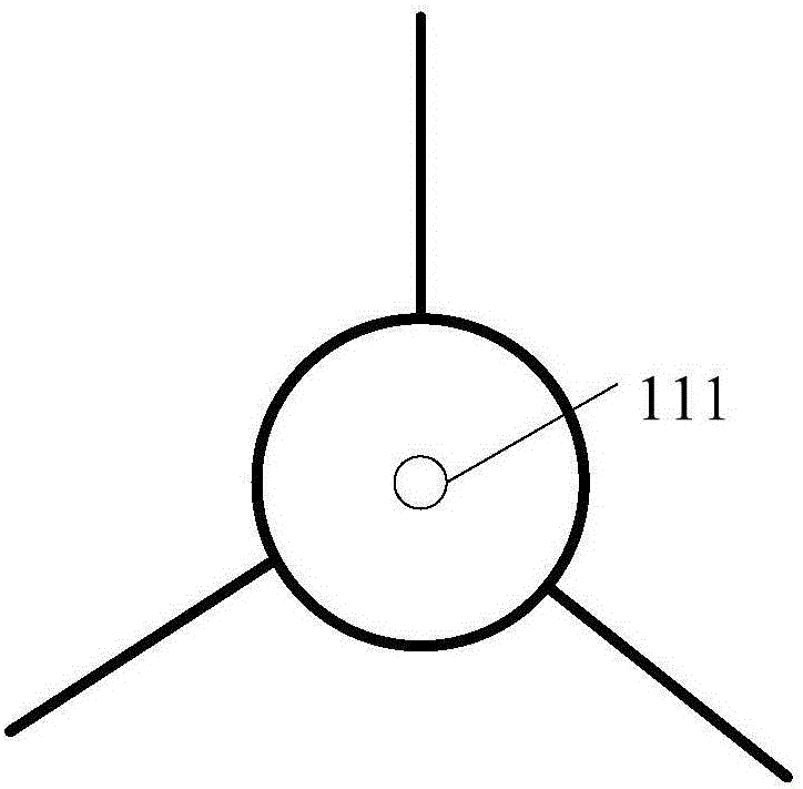
[0046] Such as Figure 2a and Figure 2b The schematic diagrams of the appearance of the liquid faucets provided in this embodiment, such as Figure 2a and Figure 2b As shown, the liquid faucet 1 includes: a main body 11 and a bracket 12 for supporting the main body, the main body 11 is provided with a liquid outlet 111, and the bracket 12 is provided with a conduit communicating with the liquid outlet;

[0047] The liquid pipeline 3 includes: a transmission pipe 31, an electric pump 32 and an electric valve 33; the transmission pipe 31 of the liquid pipeline 3 is connected to the conduit on the support 12 of the liquid faucet 1, and conducts the supply source and the liquid faucet; the electric pump 32 and the electric valve 33 Instal...

Embodiment 2

[0058] In order to illustrate the beneficial effects of the present invention, this embodiment describes in detail the arrangement scheme of the liquid pipeline of the liquid supply device and the functions supported by the liquid supply device.

[0059] In this embodiment, a liquid supply device supporting two types of liquid output is taken as an example for illustration. The liquid supply device provides water and milk respectively, and the water inlet pipe can provide cold water, warm water and hot water.

[0060] Specifically, the liquid pipeline in this embodiment includes the water inlet pipeline and the beverage inlet pipeline in Embodiment 1. For the convenience of description, the water storage device in the cold water inlet pipeline is set as a water storage tank, and the heating in the hot water inlet pipeline The device is set as a heating box (or water boiler, etc.), such as image 3 as shown, image 3 The schematic diagram of the pipeline of the liquid supply e...


PUM


Abstract

The invention discloses a liquid supply device. The device comprises a liquid faucet, a central controller and a liquid pipeline. The liquid faucet comprises a main part and a support. The main part is provided with a liquid outlet. The support is provided with a guide pipe communicating with the liquid outlet. The liquid pipeline comprises a transmission pipe, an electric pump and an electrical valve. The transmission pipe is connected to the guide pipe of the support of the liquid faucet. The electric pump and the electrical valve are arranged on the transmission pipe. The electric pump provides liquid transmission power for the liquid pipeline, and the electrical valve serves as a switch of the liquid pipeline. The central controller controls the electric pump and the electrical valve on the liquid pipeline according to a user instruction, and liquid outputting or liquid outputting stopping is achieved. Compared with the prior art, in the technical scheme, quantitative liquid outputting, automatic residual liquid recycling, automatic cleaning and other multifunctional effects can be achieved, the liquid supply device can be matched with a mobile control terminal as well to achieve non-contact and long-distance control over the liquid supply device, and a control manner is more convenient and flexible.

Description

technical field [0001] The invention relates to the technical field of the Internet of Things, in particular to a liquid supply device. Background technique [0002] Faucet is a very common household item in people's daily life, used to control the size and switch of water flow. In order to facilitate users to use hot water, the current faucet also has the function of mixing hot and cold water, so that hot or warm water can be used directly. [0003] Common faucets are mostly mechanical structures, and most of their valve cores include a moving piece and a static piece. The relative movement between the moving piece and the static piece makes the hole on the moving piece communicate with the water inlet hole on the static piece. The hole communicates with the water outlet channel so that hot water can be mixed into the faucet. After this kind of hot and cold water faucet is opened, people can't know the temperature of the water outlet, they can only test it by hand, and it...

Claims


Application Information

Patent Timeline
Patent Type & Authority Applications(China)
IPC IPC(8): F17D1/14F17D1/08F17D3/01F17D3/18F24H1/18F04C11/00F04C14/00F04B43/12F04B49/06E03B7/07E03B1/04F16K31/02
CPCA47J31/46E03B1/04E03B7/078F04B43/0081F04B43/12F04C11/008F04C14/00F16K31/02F17D1/082F17D1/084F17D1/14F17D3/01F17D3/18F24H1/181
Inventor 张阳张可志李永坡王建亮
Owner BUBBLE LAB CO LTD
Why Eureka
Try Eureka