Supercharge Your Innovation With Domain-Expert AI Agents!

Ventilation and heat dissipation structure for LED lamp

A technology for ventilation and heat dissipation and LED lamps, which is applied to lighting and heating equipment, cooling/heating devices for lighting devices, lighting devices, etc. The effect of ensuring heat dissipation and improving the heat dissipation effect

Active Publication Date: 2016-07-06
ZHEJIANG CHENFENG SCIENCE AND TECHNOLOGY CO LTD
View PDF4 Cites 0 Cited by
  • Summary
  • Abstract
  • Description
  • Claims
  • Application Information

AI Technical Summary

Problems solved by technology

like figure 1 and figure 2 As shown, the LED lamp is usually composed of a glass bulb 5, a lamp cup 1, a connector 2, and a lamp holder 3, wherein a heat dissipation cover 4 is provided at the mouth of the lamp cup, and a light-emitting electrical element 42 is arranged on the heat dissipation cover 4. The lamp cup 1 is connected and fixed to the lamp holder 3, and its main heat dissipation method is the heat sink 10 provided on the outer wall of the lamp cup 1, and the current conventional technology of the lamp cup is made by pressure injection and machining, that is, the After the aluminum is liquefied, it is injected into the cavity of the mold through the injection equipment. The disadvantages of this method are high production cost, low production efficiency, and the heat dissipation effect is not ideal.

Method used


Image

  • Ventilation and heat dissipation structure for LED lamp
  • Ventilation and heat dissipation structure for LED lamp
  • Ventilation and heat dissipation structure for LED lamp

Examples


Embodiment Construction

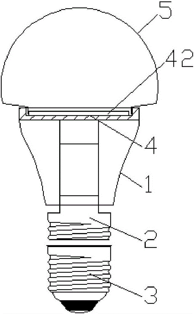
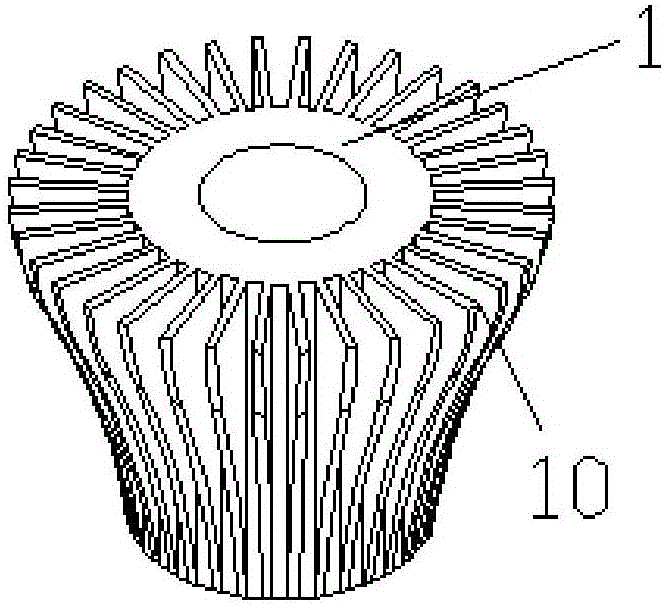
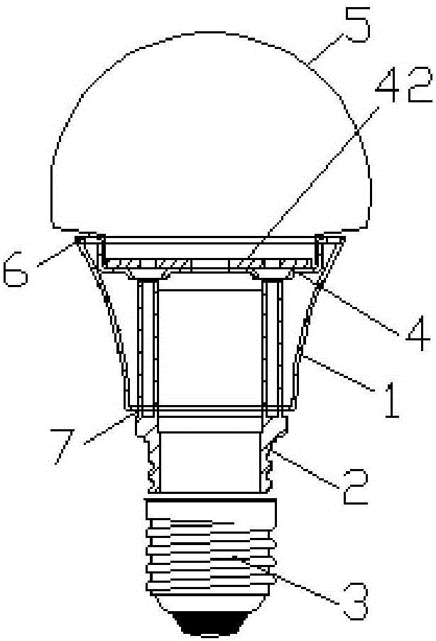
[0018] Such as Figure 3 to Figure 7 As shown, a heat dissipation structure of an LED lamp includes an aluminum lamp cup 1, the mouth of the lamp cup is connected to a glass bulb 5, a heat dissipation cover 4 is provided inside the mouth of the lamp cup, and a light-emitting electrical element 42 is installed on the heat dissipation cover. The bottom of the lamp cup is connected to the lamp holder 3 through the connecting piece 2. The heat dissipation cover 4 includes a cover body 40. A central hole 401 is opened in the center of the bottom of the cover body. Two side holes 402 are symmetrically opened on both sides of the center hole on the central axis of the bottom of the cover body. , the wire passes through the central hole 401 to connect with the light-emitting electrical element 42 and the lamp cap, and the mouth of the cover is provided with a circle of outward turning edge 41, and the outer turning edge 41 is uniformly opened with cooling holes 411 along the circumfere...


PUM


Abstract

The invention discloses a ventilation and heat dissipation structure for an LED lamp. The ventilation and heat dissipation structure comprises an aluminium lamp cup, wherein the bottom of the lamp cup is connected with a lamp holder through a connection element; a heat dissipation port is arranged between a bottom opening of the lamp cup and the connection element; the heat dissipation port is communicated with the inner cavity of the lamp cup; an inner convex ring is arranged at the inner side of the bottom opening of the lamp cup; the inner convex ring is peripherally provided with a crenel groove; the heat dissipation port is formed between the crenel groove and the cylindrical outer wall of the connection element; and an outer convex ring is peripherally uniformly provided with two upwards-bulged bosses for being clamped in the crenel groove. According to the ventilation and heat dissipation structure disclosed by the invention, the heat dissipation port is arranged between the bottom opening of the lamp cup and the connection element, and the heat dissipation port is communicated with the inner cavity of the lamp cup to form a heat dissipation channel for air flowing; and in addition, the aluminium lamp cup has a heat dissipation effect, therefore, heat discharge is guaranteed in a manner of combining air convection with metal heat absorption, and the heat dissipation effect is greatly improved.

Description

[0001] The patent application of the present invention is a divisional application of the invention title "A LED Lamp Heat Dissipation Structure". The filing date of the original application is March 24, 2014, and the application number is 2014101107218. technical field [0002] The present invention relates to LED lamps. Background technique [0003] With the development of LED, it is gradually known to people. Compared with ordinary lights, LED lights have the advantages of long life, energy saving, and environmental protection, and are valued by enterprises of all sizes. However, the high cost of its production has slowed down its entry into ordinary families. LEDs will generate heat during use. If the heat is not dissipated in time, the service life of LED lights will be greatly affected. Therefore, the heat sink of LED lights is usually made of aluminum. Such as figure 1 and figure 2 As shown, the LED lamp is usually composed of a glass bulb 5, a lamp cup 1, a conn...

Claims


Application Information

Patent Timeline
Patent Type & Authority Applications(China)
IPC IPC(8): F21K9/20F21V29/83F21V29/89F21Y115/10
CPCF21V29/83F21V29/89
Inventor 徐建宁何文联
Owner ZHEJIANG CHENFENG SCIENCE AND TECHNOLOGY CO LTD
Features
  • R&D
  • Intellectual Property
  • Life Sciences
  • Materials
  • Tech Scout
  • Unparalleled Data Quality
  • Higher Quality Content
  • 60% Fewer Hallucinations
Learn More