Supercharge Your Innovation With Domain-Expert AI Agents!

Jump wire device and method

A flying lead and main insulation technology, applied in the field of electric power, can solve the problems of low efficiency and poor safety of high-voltage flying leads, and achieve the effects of high electrical and mechanical strength, high safety, and detachable components

Active Publication Date: 2016-07-06
YUNNAN POWER GRID CO LTD ELECTRIC POWER RES INST
View PDF6 Cites 4 Cited by
  • Summary
  • Abstract
  • Description
  • Claims
  • Application Information

AI Technical Summary

Problems solved by technology

[0005] The embodiment of the present invention provides a flying wire device and method to solve the problems of low efficiency and poor safety of high-voltage flying wires in the prior art

Method used


Image

  • Jump wire device and method
  • Jump wire device and method
  • Jump wire device and method

Examples


Embodiment 1

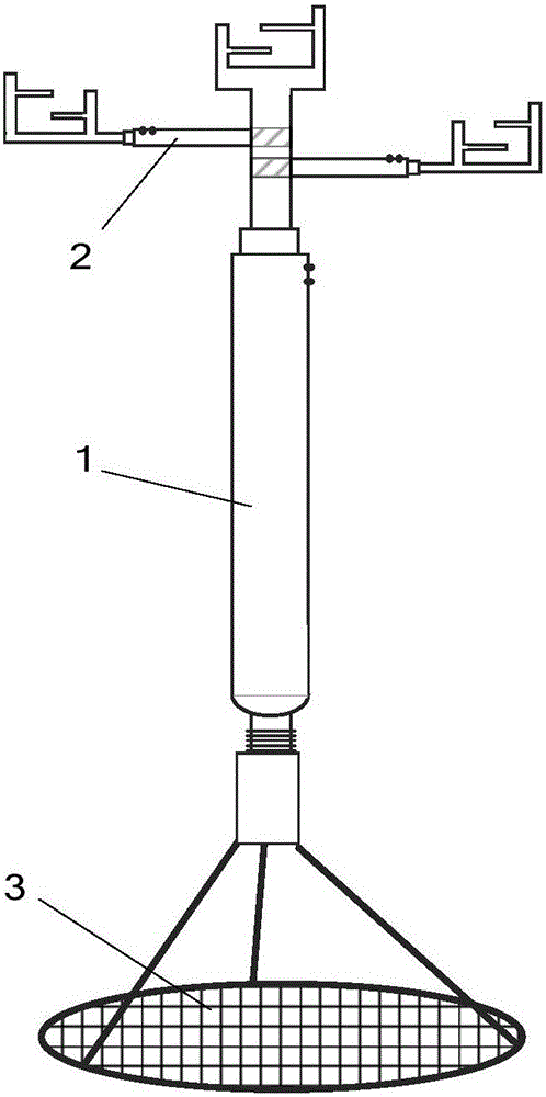
[0041] see figure 1 , is a schematic structural diagram of a flying lead device provided by an embodiment of the present invention, the flying lead device includes a main insulating rod 1 , a side insulating rod 2 and a fixed support 3 .

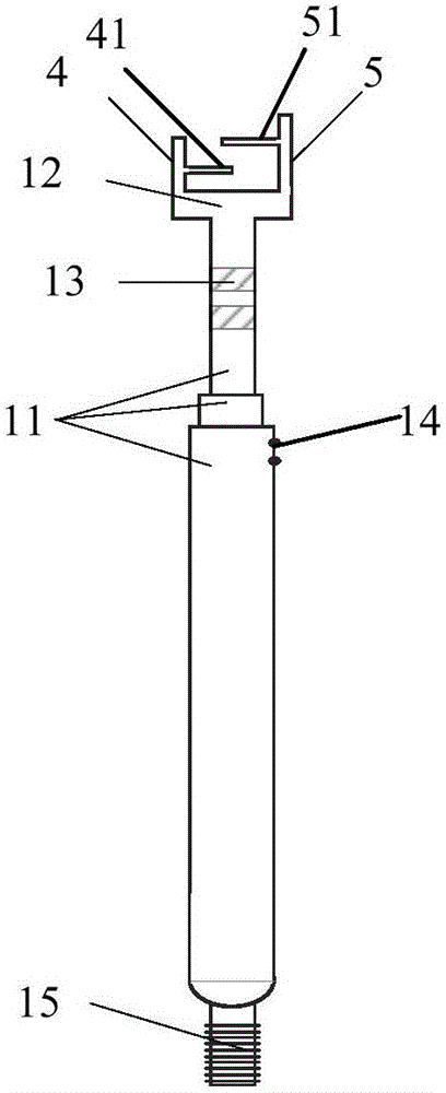
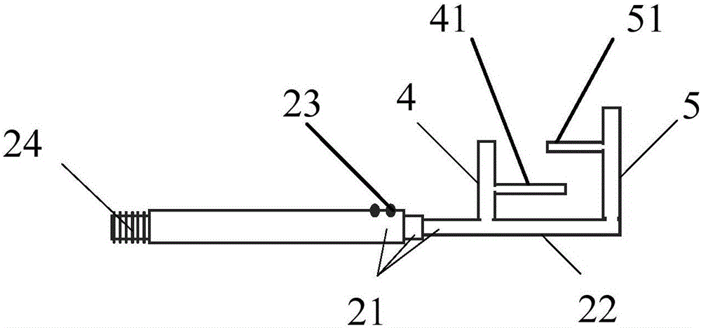
[0042] Among them, see figure 2 , is a schematic structural diagram of a main insulating rod provided by an embodiment of the present invention. The main insulating rod 1 includes a main insulating rod telescopic section 11 , a top fork 12 , a screw hole 13 , a main insulating buckle 14 and a main insulating bolt 15 . In the embodiment of the present invention, the main insulating rod 1 includes three main insulating rod telescopic joints 11, which are convenient for users to adjust the length. The above-mentioned expansion joint structure is a commonly used structure and will not be described in detail here. Of course, in actual implementation, the number of the main insulation rod expansion joints 11 can be any value, and the length and ...

Embodiment 2

[0050] see Figure 5 , is a structural schematic diagram of another fixed support provided by the embodiment of the present invention. The difference between the embodiment of the present invention and the first embodiment is that the fixed support in the implementation of the present invention is Figure 5 Pneumatic mounts shown. Specifically, the fixed support 3 includes an air pressure connection nut 34, an air pressure suction cup 35 and an air nozzle 36; wherein, the air pressure connection nut 34 matches the main insulating rod bolt 15, and the fixed support 3 is connected by the air pressure The screw mesh 34 is connected with the main insulating rod 1; the air pressure chuck 35 is an air pressure chuck including a suction cup cavity, and the air nozzle 36 is arranged on the top surface of the air pressure chuck 35 and is connected with the suction cup cavity. connected. For the similarities between the embodiment of the present invention and the first embodiment, ref...


PUM


Abstract

The embodiment of the present invention discloses a jump wire device and method. The jump wire device comprises a main insulating rod, a side insulating rod and a fixing support, the main insulating rod and the side insulating rod are both the insulating rods with a plurality of telescopic sections, and the top of the main insulating rod is fixedly equipped with a top fork. One end part of the side insulating rod is connected with the main insulating rod detachably, and the other end part is fixedly equipped with a side fork, and the bottom of the main insulating rod is connected with the fixing support movably. At the actual use, the jump wire device is placed at a corresponding position, the side insulating rod is arranged at the corresponding position of the main insulating rod according to demands, at the same time, the lengths of the main insulating rod and the side insulating rod are adjusted according to a jump wire distance and the safe separation distance of the voltage applying wires, and the voltage applying wires are fixed and tightened by utilizing the top fork and the side fork. The safe distances are maintained between the voltage applying wires and between the voltage applying wires and the power equipment, so that the voltage applying wires are not easy to fall off, and the jump wire device has a very high safety. Moreover, the technical personnel do not need to climb the high-voltage power equipment, and the jump wire device is adjustable in length, is detachable, is convenient to arrange, and enables the jump wire efficiency to be improved.

Description

technical field [0001] The invention relates to the field of electric power technology, in particular to a flying lead device and method. Background technique [0002] Power equipment needs to be tested and inspected during delivery, handover, and operation. It is the key to ensure the normal progress of the test to conduct high-voltage flying leads on the power equipment during the test and inspection. [0003] For large-scale power equipment such as transformers and reactors, due to their large size, many accessories, and limited space on the test site, high-voltage flying leads are often very difficult. For example, when conducting transformer induction withstand voltage and partial discharge tests, the pressurized line needs to be led from the high-voltage test device on the ground to the top wiring board of the transformer low-voltage bushing. The transformer may be several meters high and several meters wide, surrounded by live equipment , the space of the test site i...

Claims


Application Information

Patent Timeline
IPC IPC(8): G01R31/00G01R31/12
CPCG01R31/00G01R31/12
Inventor 刘光祺项恩新钱国超邹德旭颜冰
Owner YUNNAN POWER GRID CO LTD ELECTRIC POWER RES INST
Features
  • R&D
  • Intellectual Property
  • Life Sciences
  • Materials
  • Tech Scout
  • Unparalleled Data Quality
  • Higher Quality Content
  • 60% Fewer Hallucinations
Learn More