Eureka AIR delivers breakthrough ideas for toughest innovation challenges, trusted by R&D personnel around the world.

Array substrate and manufacturing method therefor

A technology of array substrate and substrate substrate, which is applied in semiconductor/solid-state device manufacturing, electrical components, electrical solid-state devices, etc., can solve the problem of increased contact resistance between signal wires and pixel electrodes, incomplete exposure at the bottom of via holes in the Resin layer, TactTime (The increase in processing time and other problems can reduce the difficulty of exposure, improve production efficiency, and avoid photoresist residues.

Inactive Publication Date: 2016-07-06
BOE TECH GRP CO LTD
View PDF8 Cites 5 Cited by
  • Summary
  • Abstract
  • Description
  • Claims
  • Application Information

AI Technical Summary

Problems solved by technology

[0002] In the structure of the existing array substrate, a passivation layer and a resin layer are formed on the source-drain metal layer. The thickness of the resin layer is generally relatively large, and the thickness of the passivation layer is added. Incomplete exposure or residual photoresist at the bottom of the via hole in the Resin layer will cause the contact resistance between the signal wire and the pixel electrode to increase or even not conduct, which will directly lead to the failure of the display device
The existing method is to increase the exposure energy, which will lead to an increase in TactTime (processing time) and a decrease in production capacity

Method used


Image

  • Array substrate and manufacturing method therefor
  • Array substrate and manufacturing method therefor
  • Array substrate and manufacturing method therefor

Examples


Embodiment Construction

[0025] In order to make the technical problems, technical solutions and advantages to be solved by the present invention clearer, the following will describe in detail with reference to the drawings and specific embodiments.

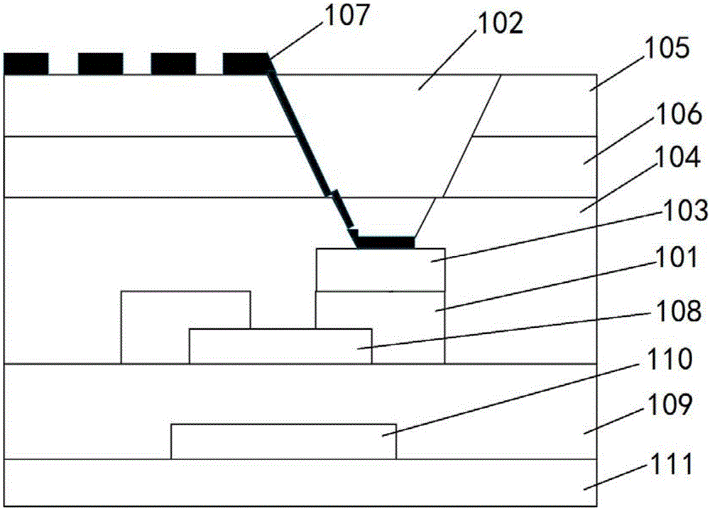
[0026] The present invention firstly provides an array substrate with a structure such as figure 1 As shown, it includes: a first conductive pattern 101, an insulating layer covering the first conductive pattern 101 and including a via hole 102, and a second conductive pattern is provided on the first conductive pattern corresponding to the position of the via hole 102 103.

[0027] It can be seen from the above that the array substrate provided by the present invention is provided with a second conductive pattern under the via hole in the insulating layer, and the second conductive pattern can reduce the depth of the via hole and increase the height of the bottom of the via hole. function, thereby reducing the difficulty of exposure at the bottom of th...


PUM


Abstract

The invention provides an array substrate and a manufacturing method therefor. The array substrate comprises a first conductive pattern, wherein the first conductive pattern is covered with an insulating layer with a via hole; a second conductive pattern is arranged in a position, corresponding to the position of the via hole, on the first conductive pattern; and the manufacturing method for the array substrate comprises the step of forming the second conductive pattern in the position, corresponding to the position of the via hole, on the first conductive pattern. By adoption of the array substrate and the manufacturing method therefor provided by the invention, the condition of incomplete exposure or photoresist residue at the bottom of the via hole can be reduced or avoided.

Description

technical field [0001] The invention relates to the technical field of liquid crystal display, in particular to an array substrate and a manufacturing method thereof. Background technique [0002] In the structure of the existing array substrate, a passivation layer and a resin layer are formed on the source-drain metal layer, and the thickness of the resin layer is generally relatively large. In addition, when the thickness of the passivation layer is added, when the resin layer is exposed, it will Incomplete exposure or residual photoresist at the bottom of the via hole in the Resin layer will cause the contact resistance between the signal wire and the pixel electrode to increase or even not conduct, directly leading to the failure of the display device. The existing method is to increase the exposure energy, which will lead to an increase in TactTime (processing time) and a decrease in production capacity. Contents of the invention [0003] In view of this, the presen...

Claims


Application Information

Patent Timeline
Patent Type & Authority Applications(China)
IPC IPC(8): H01L27/12H01L21/77
CPCH01L27/124H01L27/1288
Inventor 刘兴东吴旭沈武林江峰
Owner BOE TECH GRP CO LTD
Why Eureka
Eureka Blog
Learn More