Swing motor and electric clipper

A swing motor and control circuit technology, applied in electrical components, electromechanical devices, metal processing, etc., can solve the problems of small torque, electric clippers cannot be designed as wireless portable, and cannot generate working torque, etc., to achieve stable driving current , Energy-saving effect is obvious, the effect of long battery life

Active Publication Date: 2016-07-06
胡建坤
View PDF8 Cites 8 Cited by
  • Summary
  • Abstract
  • Description
  • Claims
  • Application Information

AI Technical Summary

Problems solved by technology

If this structure uses a rechargeable battery as a low-voltage drive, the torque is very small and cannot generate working torque, that is, this type of electric clipper cannot be designed as a wireless portable

Method used


Image

  • Swing motor and electric clipper
  • Swing motor and electric clipper
  • Swing motor and electric clipper

Examples


Embodiment 1

[0045] Embodiment 1 provides a swing motor that can output a reciprocating swing motion.

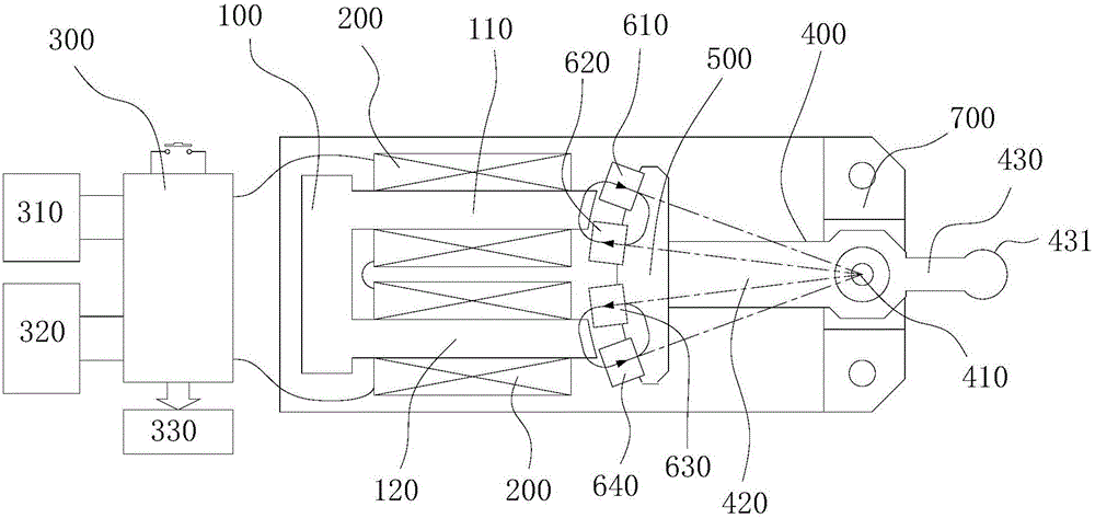
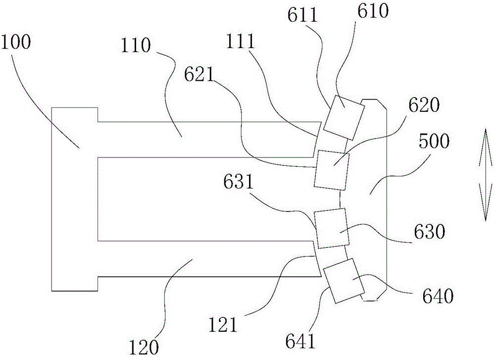
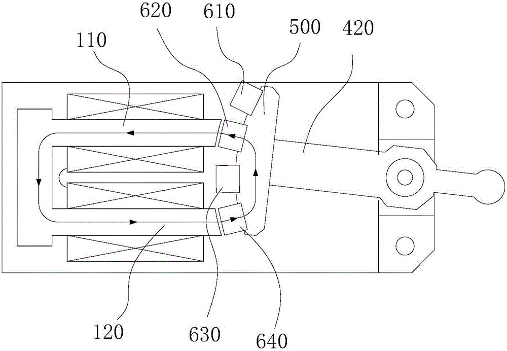
[0046] Please refer to figure 1 with 2 , the swing motor consists of:

[0047] A U-shaped yoke 100, the U-shaped yoke 100 has a first leg 110 and a second leg 120, coils 200 are respectively wound on the first leg 110 and the second leg 120;

[0048] A control circuit 300, the control circuit 300 is electrically connected to the coil 200, and generates alternating pulses, so that the end faces 111 and 121 of the two legs of the U-shaped magnetic yoke 100 generate alternating magnetic poles;

[0049] A swing arm 400 that can swing around a fulcrum. The swing arm 400 extends outward from the end faces 111 and 121 of the U-shaped magnetic yoke 100, and is bounded by the fulcrum. The end of the swing arm 400 close to the U-shaped magnetic yoke 100 is an inner arm 420. The end of the arm 400 away from the U-shaped yoke 100 is the outer arm 430;

[0050] The second yoke 500 (in order to di...

Embodiment 2

[0075] Embodiment 2 provides another swing motor.

[0076] Please refer to Figure 9 , the swing motor is improved on the structure shown in the first embodiment.

[0077] Specifically, elastic bodies 810 are provided on both sides of the swing arm 400 for absorbing the moment of inertia of the swing arm 400 when swinging in place, and the elastic characteristics of the elastic bodies 810 are curves of more than two degrees.

[0078] Wherein, the elastic body 810 is mainly used to absorb the moment of inertia of the swing arm 400 in the no-load state, and its elastic force increases with the increase of the compression stroke. The elastic characteristics of the elastic body 810 can ensure that the elastic body 810 does not have too much influence on the swing of the swing arm 400 under the load state (the swing distance of the swing arm 400 will be attenuated under the load state), only the swing arm 400 is squeezed too much under the no-load state Only the elastic body 810 ...

Embodiment 3

[0086] Embodiment 3 provides another swing motor.

[0087] Please refer to Figure 10 , the swing motor is improved on the structure shown in the first embodiment, and a resonant elastic member for generating resonance at a constant swing frequency is added.

[0088] Specifically, one end of the resonant elastic member is fixed on the fulcrum of the swing arm, and the other end is connected to the outer arm or the inner arm.

[0089] further, Figure 10 The resonant elastic member shown in is a straight spring steel wire, in addition, other shapes of elastic members can also be used instead, such as Figure 11 The middle portion of the resonant elastic member shown is curved.


PUM


Abstract

The invention discloses a swing motor and an electric clipper. The swing motor comprises a U-shaped magnet yoke, four permanent magnets and a swing arm, wherein the U-shaped magnet yoke can make the end surfaces of two stand bars generate alternating magnetic poles under a control circuit; the four permanent magnets are fixedly arranged on an inner arm through a second magnet yoke; the four permanent magnets are a first permanent magnet, a second permanent magnet, a third permanent magnet and a fourth permanent magnet respectively and are sequentially distributed on the same circumference employing the pivot as the circle center; the radial end surfaces of the first permanent magnet and the fourth permanent magnet are the same in polarity; the radial end surfaces of the second permanent magnet and the third permanent magnet are the same in polarity and are opposite to the radial end surface of the first permanent magnet in polarity; and when a coil is electrified, the four permanent magnets generate torques which are the same in rotating direction, thereby swinging in a reciprocating manner under the action of the two stand bars of the U-shaped magnet yoke. The permanent magnet redundancy design is a motor magnetic circuit design different from that in the prior art; the swing motor is larger in torque than an existing same-power motor; and the drive power is correspondingly reduced if the acting magnetic flux is high.

Description

technical field [0001] The present application relates to an electric motor, especially an electric motor capable of outputting an oscillating motion. Background technique [0002] The motor is an electromagnetic device that realizes the conversion of electric energy according to the law of electromagnetic induction. It is widely used in various fields and is an indispensable prime mover in today's society, providing a power source for a large number of electrical appliances or various machinery. [0003] Electric clippers are a kind of equipment with motor as the power mechanism. At present, the motors of electric clippers are divided into rotary motors and swing motors. A rotating electrical machine is a rotating electromagnetic machine that operates on the principle of electromagnetic induction. It is used to realize the mutual conversion of mechanical energy and electrical energy. At the same time, the rotating electrical machine uses a transmission mechanism to convert ...

Claims


Application Information

Patent Timeline
Patent Type & Authority Applications(China)
IPC IPC(8): H02K33/02H02K33/14B26B19/12B26B19/28
CPCB26B19/12B26B19/28H02K33/02H02K33/14
Inventor 胡建坤胡建长胡斐然胡斐凡
Owner 胡建坤
Why Eureka
Try Eureka