Switching device comprising an electromagnetic arc driving mechanism

A switchgear and drive mechanism technology, applied in the field of switchgear, can solve the problems of no mechanical support, insufficient use of the entire volume of the arc extinguishing chamber, short arc guide pieces, etc., and achieve the effect of improving the magnetic force

Active Publication Date: 2016-07-06
SIEMENS AG
View PDF6 Cites 4 Cited by
  • Summary
  • Abstract
  • Description
  • Claims
  • Application Information

AI Technical Summary

Problems solved by technology

As a rule, the arc guides, which are kept short, either have no mechanical support at all, or additional plastic parts are used for support, but this leads to additional costs
Soluti

Method used


Image

  • Switching device comprising an electromagnetic arc driving mechanism
  • Switching device comprising an electromagnetic arc driving mechanism
  • Switching device comprising an electromagnetic arc driving mechanism

Examples


Embodiment Construction

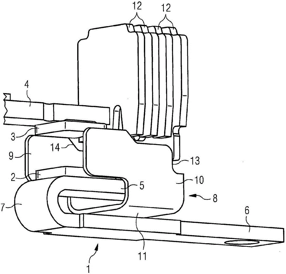
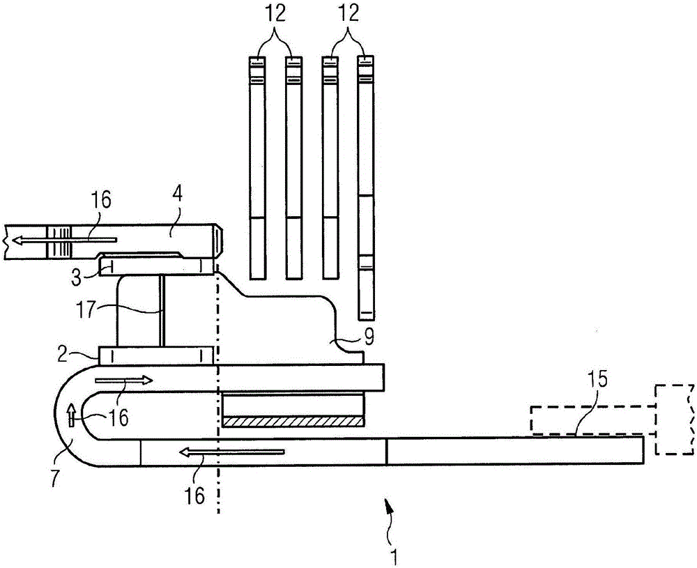
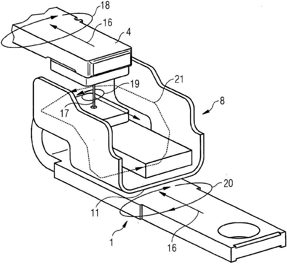
[0034] figure 1 The arrangement of components in an interrupter of a switchgear is shown. There is a fixedly positioned contact 1 with a contact 2 which is arranged opposite a contact 3 of a movable contact 4 . The fixedly positioned contact 1 is preferably designed as a U with two legs 5, 6 and a connection region 7 connecting the two legs 5, 6 to each other, which legs can be of different lengths and connected to each other. parallel. also, figure 1 The electromagnetic arc drive and the connecting intermediate part 11 are shown in the form of a metal sheet 8 which is preferably designed in a U-shape with two legs 9 , 10 which are preferably parallel and congruent to one another. The connecting intermediate part 11 of the sheet metal 8 is preferably arranged between the legs 5 , 6 of the fixedly positioned contact 1 . A quenching plate 12 is preferably arranged above the region of the connecting intermediate part 11 of the metal sheet 8 . The legs 9 , 10 of the metal she...


PUM


Abstract

The invention relates to a switching device comprising an electromagnetic arc driving mechanism and an arcing chamber that includes a stationary switching piece (1) and an opposite movable switching piece (4). The invention is characterized in that the electromagnetic arc driving mechanism is embodied in the form of a metal sheet (8) that is placed around the stationary switching piece (1).

Description

technical field [0001] The invention relates to a switchgear with an electromagnetic arc drive, wherein the switchgear has an arc quenching chamber with fixedly positioned contacts and movable contacts arranged opposite thereto. Background technique [0002] In such switching devices, an arc is generated at the open contacts when the current is switched off. Burning of the arc through the contact material causes losses at the contacts and delays opening of the circuit as current continues to flow through the arc until the arc is extinguished. In order to limit the damage caused by electric arcs, electrical switching devices or protective devices are equipped with arc quenching devices starting from a certain power. [0003] Such arc quenching devices often consist of an arc quenching chamber with arc guides and various components, which also fulfill current-technical purposes. [0004] The quenching chamber is often designed as a set of quenching plates punched into a U sh...

Claims


Application Information

Patent Timeline
IPC IPC(8): H01H9/34H01H9/44
CPCH01H9/346H01H9/446
Inventor 路德维希·尼布乐瓦津姆·库利诺维奇托比亚斯·菲豪泽
Owner SIEMENS AG
Why Eureka
Try Eureka