Brush roller with double bearing pedestals

A technology of double bearings and moving bearing seats, which is applied to the cleaning method using tools, cleaning methods and utensils, chemical instruments and methods, etc., which can solve the problems of unusable, cost waste, and insufficient extrusion, so as to improve the service life , cost reduction, and simple structure

Active Publication Date: 2016-07-13
WISDRI ENG & RES INC LTD
View PDF7 Cites 3 Cited by
  • Summary
  • Abstract
  • Description
  • Claims
  • Application Information

AI Technical Summary

Problems solved by technology

In the existing brushing machine, the position of the brush roller is generally fixed, and the structure of the fixed brush roller causes uneven wear of the bristles, which is specifically reflected in that when the strip steel works continuously along a certain section of the brush roller for a long time, the A micro-groove with the same shape as the strip steel is ground at the corresponding position of the brush roller. Afterwards, when the specification of the strip steel needs to be changed, the brush roller cannot squeeze the strip steel due to the groove, so that the gap between the strip steel and the lower roller The rolling friction between them becomes sliding friction, and the lower roller will wear out rapidly due to sliding friction until it cannot be used, resulting in waste of cost. At the same time, the surface of the strip is not cleaned, which affects the processing quality of the strip.

Method used


Image

  • Brush roller with double bearing pedestals
  • Brush roller with double bearing pedestals

Examples


Embodiment Construction

[0015] The present invention will be further described below in conjunction with the accompanying drawings and embodiments.

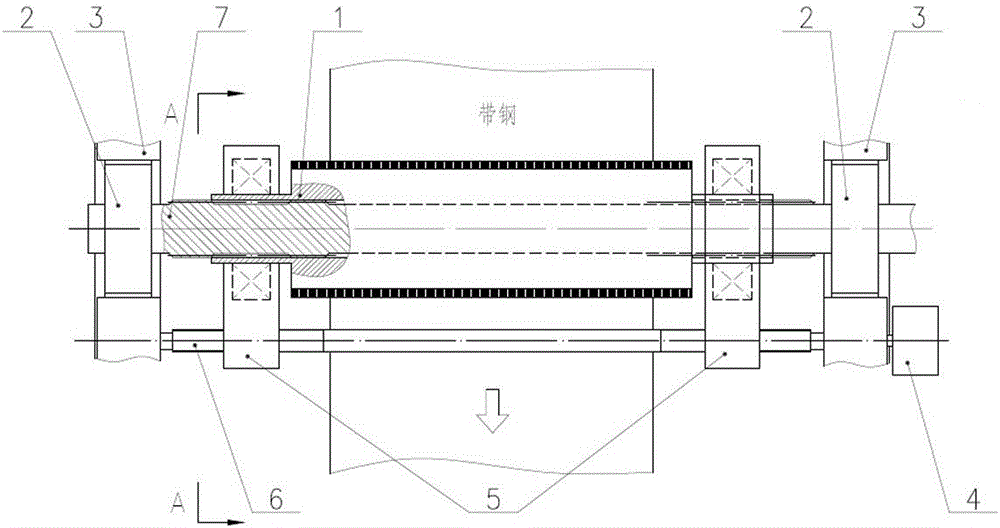
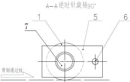
[0016] Such as figure 1 As shown, a brush roller with a double bearing seat includes a brush roller shaft 7 and a brush roller 1, the brush roller 1 is provided with bristles, and the brush roller 1 is set on the brush roller shaft 7 and passes through the splines The two ends of the brush roller shaft 7 pass through the brush roller 1 respectively and are respectively arranged on a fixed bearing seat 2. The two fixed bearing seats 2 are respectively arranged on a frame 3. The two ends of the brush roller 1 Each is arranged on a movable bearing seat 5, and a lead screw 6 respectively fits through the two movable bearing seats 5 and is parallel to the brush roller shaft 7. One end of the lead screw 6 is arranged on a frame 3, and the other end passes through the The other frame 3 is also connected with the driving mechanism 4, and the driving mechanism ...


PUM


Abstract

The invention relates to a brush roller with double bearing pedestals.The brush roller comprises a brush roller shaft and a brush roller cylinder.Bristles are arranged on the brush roller cylinder.The brush roller shaft is sleeved with the brush roller cylinder and matched and connected with the brush roller cylinder through spline.The two ends of the brush roller shaft penetrate out of the brush roller cylinder and are arranged on the fixed bearing pedestals respectively.The two fixed bearing pedestals are arranged on machine frames respectively.The two ends of the brush roller cylinder are arranged on the movable bearing pedestals respectively.A lead screw penetrates through the two movable bearing pedestals in a matched mode to be parallel to the brush roller shaft.One end of the lead screw is arranged on one machine frame, and the other end of the lead screw penetrates through the other machine frame and is connected with a drive mechanism.The drive mechanism can drive the movable bearing pedestals and the brush roller cylinder through the lead screw to reciprocate axially.All the bristles of the brush roller can make uniform contact with belt steel, and the brush roller is simple in structure and low in cost.

Description

technical field [0001] The invention belongs to the field of brushing equipment, in particular to a brush roller with double bearing seats. Background technique [0002] The equipment in the cleaning section of the strip processing line is generally equipped with a scrubbing machine. The scrubbing machine is mainly used to remove the scale on the surface of the strip and a large number of tiny foreign matter remaining in the pickling and alkali cleaning lines, so as to improve the surface quality of the strip. In the existing brushing machine, the position of the brush roller is generally fixed, and the structure of the fixed brush roller causes uneven wear of the bristles, which is specifically reflected in that when the strip steel works continuously along a certain section of the brush roller for a long time, the A micro-groove with the same shape as the strip steel is ground at the corresponding position of the brush roller. Afterwards, when the specification of the stri...

Claims


Application Information

Patent Timeline
IPC IPC(8): B08B1/02
CPCB08B1/20B08B1/12
Inventor 滕英才艾晶
Owner WISDRI ENG & RES INC LTD
Why Eureka
Try Eureka