Bending device of electric heating wire

A bending device and electric heating wire technology, applied in the field of mechanical tooling, can solve problems such as limited scope of application, and achieve the effects of convenient bending radius, convenient switching, and simple structure

Active Publication Date: 2016-07-13
扬州欣泰电热元件制造有限公司
View PDF9 Cites 4 Cited by
  • Summary
  • Abstract
  • Description
  • Claims
  • Application Information

AI Technical Summary

Problems solved by technology

[0002] In the prior art, in the manufacturing process of the electric heating wire, it is necessary to bend the resistance wire. The bendin

Method used


Image

  • Bending device of electric heating wire
  • Bending device of electric heating wire
  • Bending device of electric heating wire

Examples


Embodiment Construction

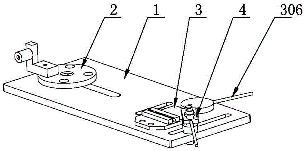
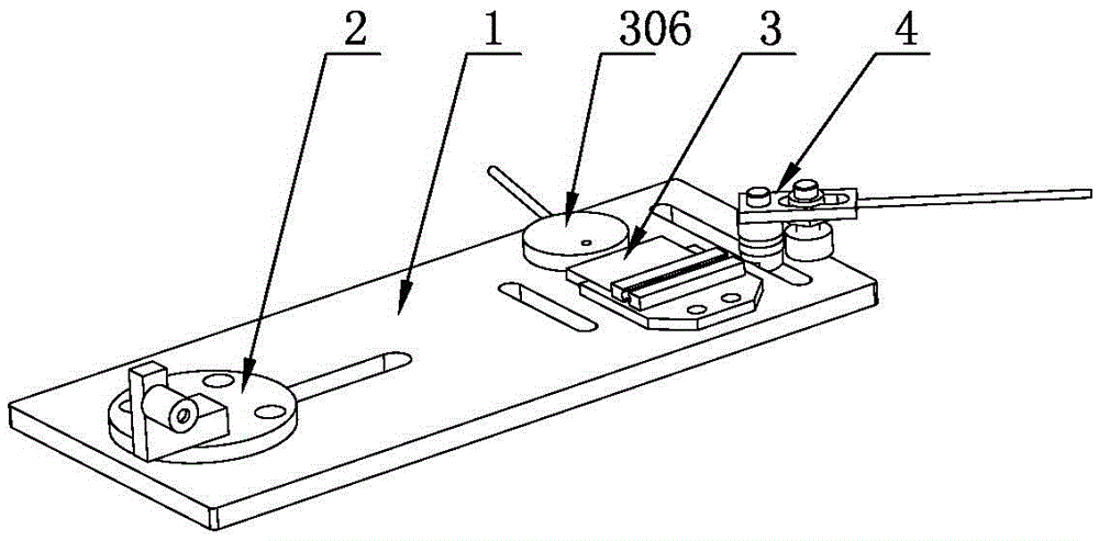
[0019] Such as Figure 1-5 The electric heating wire bending device shown includes a bottom plate 1 on which a positioning mechanism 2, a clamping mechanism 3 and a bending mechanism 4 are installed;

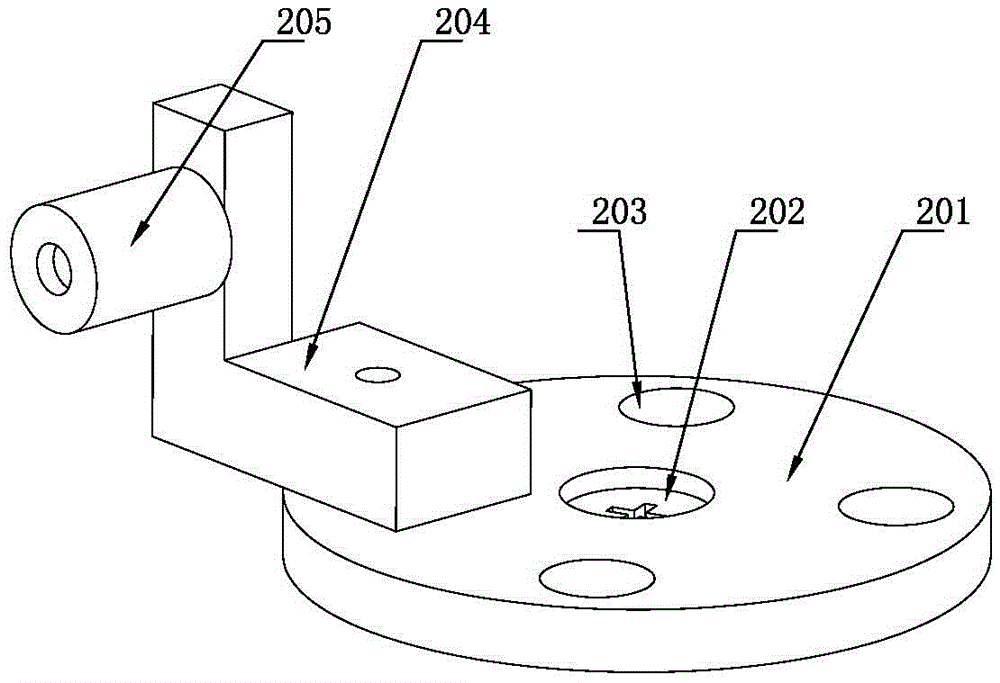
[0020] The positioning mechanism 2 includes a positioning plate 201 fixedly installed on the base plate 1, a positioning block 204 is fixedly installed on the positioning plate 201, a positioning column 205 is installed on the positioning block 204, the positioning plate 201 is slidably installed on the base plate 1, and the positioning The positioning plate 201 is rotatable, and the positioning plate 201 can be fixed on the base plate 1 by bolts 202 after sliding and rotating to a suitable position. The positioning plate 201 is evenly provided with a plurality of positioning holes 203 along its circumferential direction, and the positioning block 204 is rotatably installed on the positioning plate 1. Inside the hole 203;

[0021] The clamping mechanism 3 includes a clamping ba...


PUM


Abstract

The invention discloses a bending device of an electric heating wire in the field of fixture structures. The bending device comprises a base plate, and a positioning mechanism, a clamping mechanism and a bending mechanism which are mounted on the base plate; the positioning mechanism comprises a positioning plate fixedly mounted on the base plate, a positioning block is fixedly mounted on the positioning plate, and a positioning column is mounted on the positioning block; the clamping mechanism comprises a clamping base and a clamping slide block which are mounted on the base plate, an eccentric wheel matched with the clamping slide block is further arranged on the base plate, and the eccentric wheel rotates to drive the clamping slide block to slide in the clamping base; the bending mechanism comprises a central shaft mounted on the base plate, a center wheel is arranged on the central shaft in a sleeving manner, arc-shaped grooves are processed in the periphery of the center wheel, a rotatable wrench is further arranged on the central shaft in a sleeving manner, and an extrusion wheel matched with the center wheel is arranged on the wrench. The bending device of the electric heating wire disclosed by the invention is simple in structure, convenient to use, high in efficiency while bending, and further convenient in bending radius switching, thereby being applicable to processing of electric heating wires.

Description

technical field [0001] The invention relates to a mechanical tooling, in particular to a bending device. Background technique [0002] In the prior art, in the manufacturing process of the electric heating wire, it is necessary to bend the resistance wire. The bending radius of the existing bending device is fixed, and only copper tubes with one radius can be processed. The scope of application limited. Contents of the invention [0003] The purpose of the present invention is to provide an electric heating wire bending device, which makes bending resistance wire more convenient and improves processing efficiency. [0004] The purpose of the present invention is achieved as follows: an electric heating wire bending device, including a bottom plate, a positioning mechanism, a clamping mechanism and a bending mechanism are installed on the bottom plate; [0005] The positioning mechanism includes a positioning plate fixedly installed on the base plate, a positioning block ...

Claims


Application Information

Patent Timeline
IPC IPC(8): B21F1/00
CPCB21F1/002
Inventor 胡志新
Owner 扬州欣泰电热元件制造有限公司
Why Eureka
Try Eureka