Electric mould clamping mechanism of injection moulding machine

A technology of injection molding machine and electric lock, which is applied in the field of injection molding machine manufacturing, can solve the problems of complex and huge pulley system device structure, large error of ball screw straightness accuracy, and short service life of belt, so as to reduce technical difficulties and manufacture The effect of cost, fast mode-locking response, and short transmission distance

Active Publication Date: 2016-07-13
LIUZHOU KAIYU PLASTIC INJECTION MACHINERY CO LTD
View PDF7 Cites 2 Cited by
  • Summary
  • Abstract
  • Description
  • Claims
  • Application Information

AI Technical Summary

Problems solved by technology

[0002] The existing all-electric injection molding machine clamping mechanism is generally a servo motor through a certain amplification ratio belt pulley system, which amplifies and decelerates the torque output by the servo motor to the linear ball screw connected to it, and then the linear ball screw Drive the crosshead of the mold clamping structure to control the movement of the mold clamping part of the entire injection molding machine, and the crosshead guide rod is installed on the tail plate, and the relative deformation is relatively large
Therefore, the structure of the belt pulley system of the clamping part of this all-electric injection molding machine is relatively complex and bulky, which affects the installation of the machine, and the error of the straightness of the ball screw before and after is relatively large.
In addition, the injection molding machine with electric clamping structure of this structure needs to re-adjust the tension of the belt transmission after a certain period of use, and there are problems such as a short service life of the belt.

Method used


Image

  • Electric mould clamping mechanism of injection moulding machine

Examples


Embodiment Construction

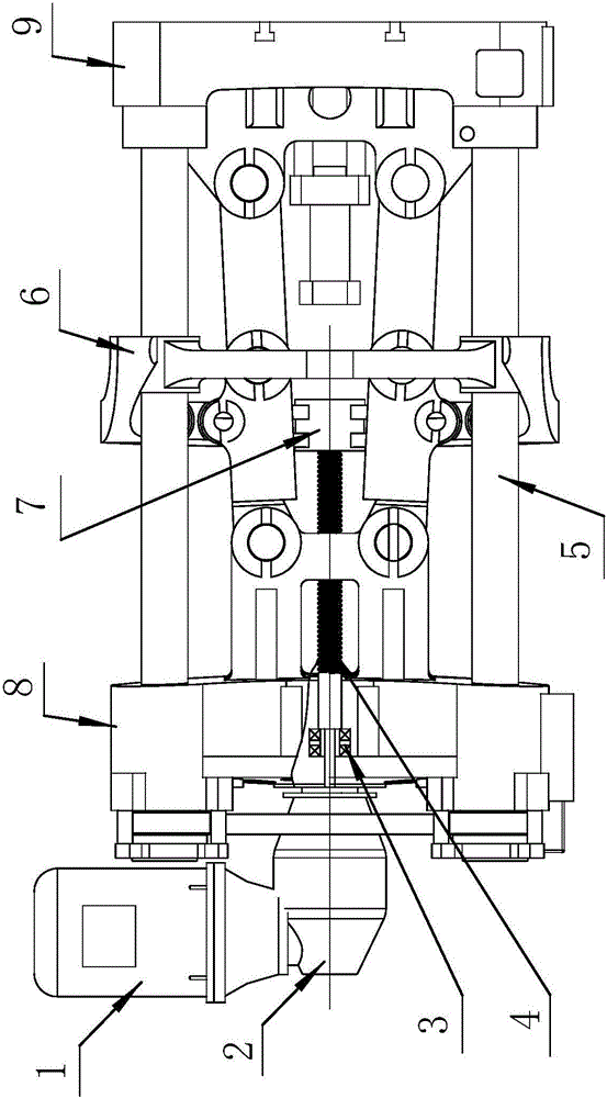
[0011] like figure 1 As shown, the electric clamping mechanism of the injection molding machine of the present invention includes a servo motor, a ball screw 4, a bearing seat 3, a crosshead 6, a screw seat 7, a tail plate 8, and a reducer. In this embodiment, the reducer The motor is a planetary reducer 2, and of course the reducer can also be a box-type reducer, etc., and the servo motor is an AC servo motor 1. The planetary reducer 2 is installed on the outer end face of the tail plate 8, the AC servo motor 1 is installed on the reducer, the front end of the AC servo motor 1 extends into the rear end of the planetary reducer 2 and is directly rigidly connected with the planetary reducer 2, this way Only one transmission part, that is, the planetary speed reducer 2 is used, and its structure is simpler compared with the existing pulley transmission technology. The AC servo motor 1 is fixedly connected to the planetary reducer 2, so that the transmission distance of the rota...


PUM


Abstract

The invention discloses an electric mould clamping mechanism of an injection moulding machine, and relates to the technical field of injection moulding machine manufacturing. The electric mould clamping mechanism comprises a servomotor, a ball screw, a bearing seat, a crosshead, a screw seat, a tail plate and a speed reducer, wherein the speed reducer is mounted on the end surface of the outer side of the tail plate; the servomotor is mounted on the speed reducer; the front end of the servomotor extends into the back end of the speed reducer and is directly, rigidly and fixedly connected with the speed reducer; the bearing seat is mounted in the middle of the tail plate; the screw seat is mounted in the middle of the crosshead; one end of the ball screw is positioned in the bearing seat, and the other end of the ball screw is mounted in the screw seat on the crosshead; an output shaft of the speed reducer is connected with the ball screw positioned at one end of the bearing seat; the crosshead is guided by four pull rods; and the planetary speed reducer is driven through the servomotor to drive the ball screw for driving the crosshead to move, so that the mould opening and closing movement of the injection moulding machine is realized. The electric mould clamping mechanism has the advantages that the structure is relatively simple, and the mechanism is convenient to mount, long in service life, relatively high in control precision and the like.

Description

technical field [0001] The invention relates to the technical field of injection molding machine manufacturing, in particular to a mold locking mechanism of an injection molding machine. Background technique [0002] The existing all-electric injection molding machine clamping mechanism is generally a servo motor through a certain amplification ratio belt pulley system, which amplifies and decelerates the torque output by the servo motor to the linear ball screw connected to it, and then the linear ball screw Drive the crosshead of the clamping structure, so as to control the movement of the clamping part of the entire injection molding machine, and the crosshead guide rod is installed on the tail plate, and the relative deformation is relatively large. Therefore, the structure of the belt pulley system of the clamping part of this all-electric injection molding machine is relatively complex and bulky, which affects the installation of the machine, and the front and rear str...

Claims


Application Information

Patent Timeline
Patent Type & Authority Applications(China)
IPC IPC(8): B29C45/66
CPCB29C45/66
Inventor 徐峻曾玉龙韦浪舟焉海峰海珉韦衍
Owner LIUZHOU KAIYU PLASTIC INJECTION MACHINERY CO LTD
Why Eureka
Try Eureka