Novel low-building type rollover-prevention device of under-hung crane

A suspension crane, anti-tipping technology, applied in the direction of safety devices, transportation and packaging, load hanging components, etc., can solve the problems of tipping, wheel negative wheel pressure, crane metal structure damage, etc., to achieve the elimination of load pressure, Effect of reduced contact gap, sensitive and fast measurement response

Inactive Publication Date: 2016-07-13
XIAN YIMU SOFTWARE TECH
View PDF0 Cites 0 Cited by
  • Summary
  • Abstract
  • Description
  • Claims
  • Application Information

AI Technical Summary

Problems solved by technology

Since increasing the length of the cantilever may lead to negative wheel pressure on one side of the crane, tipping occurs, and damage to the metal structure of the crane, therefore, it is necessary to check the stability of the crane and take anti-tipping measures

Method used


Image

  • Novel low-building type rollover-prevention device of under-hung crane

Examples


Embodiment 1

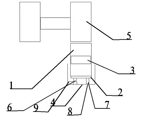
[0019] A novel anti-tipping device for low-building suspension cranes, characterized in that it includes: anti-rolling wheel 1, bearing 2, anti-rolling wheel shaft 3, anti-rolling wheel base 4, driving wheel 5; anti-rolling wheel base 4 is fixed on the end by bolts On the beam channel steel, it is used to support the anti-rolling wheel group. The gear on the anti-rolling wheel base 4 meshes with the gear on the driving wheel 5. When in use: the anti-rolling device is arranged on the end beam that will generate negative wheel pressure. When the crane When the wheel generates negative wheel pressure, the anti-roll wheel is in contact with the lower plane of the track, and the active wheel drives the anti-roll wheel to realize the running of the cart through the rotation of the anti-roll wheel.

Embodiment 2

[0021] Example 2 as figure 1 As shown, it is improved on the basis of Embodiment 1, and its anti-rolling wheel 1 adopts a flat tread wheel, and the clearance between the wheel tread and the lower plane of the track is 2 to 3 mm. Therefore, the use of flat tread wheels reduces the contact gap, and the fixed gap is within the specified range, which is helpful for the effective control of the anti-rollover device. When the distance between the anti-rolling wheel and the track is too large, the crane is prone to rollover. On the contrary, when the wheel is too tightly connected to the track, the working pressure of the crane will be too large and the efficiency will become low.

Embodiment 3

[0023] Example 3 as figure 1 As shown, it is improved on the basis of Embodiment 1. Its described anti-roller base 4 is provided with a level detector 6 and an independent oil cylinder 7, and is remotely controlled by a controller switch. Equipped with automatic detection equipment, when a tipping phenomenon is detected, the level detector controls the switch to make the independent oil cylinder act to form compensation. At the same time, the independent oil cylinder provides power, which will not affect the normal operation of the crane.


PUM


Abstract

The invention discloses a novel low-building type rollover-prevention device of an under-hung crane. The device comprises an anti-rolling wheel, a bearing, an anti-rolling wheel shaft, an anti-rolling wheel base and a drive wheel, wherein the anti-rolling wheel base is fixed on end beam channel steel by adopting a bolt, a gear on the anti-rolling wheel base is engaged with a gear on the drive wheel, the anti-rolling wheel adopts a flat-tread wheel, the anti-rolling wheel base is provided with a horizontal detector and an independent oil cylinder, a pressure sensor is disposed at the connecting part of the independent oil cylinder and the anti-rolling wheel base, and the horizontal detector is provided with a plurality of moving contacts which are horizontal and evenly distributed. An automatic detection apparatus is adopted. When a rollover phenomenon is detected, the horizontal detector controls a switch to allow the independent oil cylinder to act to form compensation. The pressure sensor is disposed to monitor pressure changes in real time, and the independent oil cylinder acts at the same time to eliminate load pressure on the roller bearing. A plurality of the contacts are used for measurement so that measurement and response are more sensitive and quicker.

Description

technical field [0001] The invention belongs to the construction application field of construction machinery, and relates to a novel anti-tipping device for a low-building suspension crane. Background technique [0002] Suspension cranes are usually designed with a certain length of cantilever, and the length of the cantilever is generally determined according to the size of the span. However, in the actual design work, sometimes in order to meet the needs of users to increase the working range of the hoist hook, the length of the crane jib needs to be increased, exceeding the range of recommended values. Since increasing the length of the cantilever may lead to negative wheel pressure on one side of the crane, tipping occurs, and damage to the metal structure of the crane, therefore, it is necessary to check the stability of the crane and take anti-tipping measures. [0003] The invention is a novel anti-tipping device for a low-building suspension crane, which is mainly u...

Claims


Application Information

Patent Timeline
Patent Type & Authority Applications(China)
IPC IPC(8): B66C15/00
Inventor 赵腾
Owner XIAN YIMU SOFTWARE TECH
Why Eureka
Try Eureka