
Special claw type rotor profile

A rotor profile and special claw technology, applied in the direction of rotary piston pump, rotary piston machine, rotary piston/oscillating piston pump components, etc., can solve the problem of low pumping speed, poor practical performance and low volume utilization coefficient And other issues

Active Publication Date: 2016-07-13
伯仲(山东)工业设备有限公司
View PDF4 Cites 14 Cited by
  • Summary
  • Abstract
  • Description
  • Claims
  • Application Information

AI Technical Summary

Problems solved by technology

Existing claw vacuum pumps mostly use single claw profile, resulting in low volume utilization coefficient of the pump, low pumping speed and poor practical performance

Method used


Image

  • Special claw type rotor profile
  • Special claw type rotor profile
  • Special claw type rotor profile

Examples


Embodiment Construction

[0055] Embodiments of the present invention are further described below in conjunction with accompanying drawings:

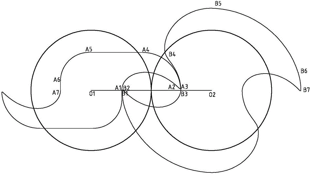
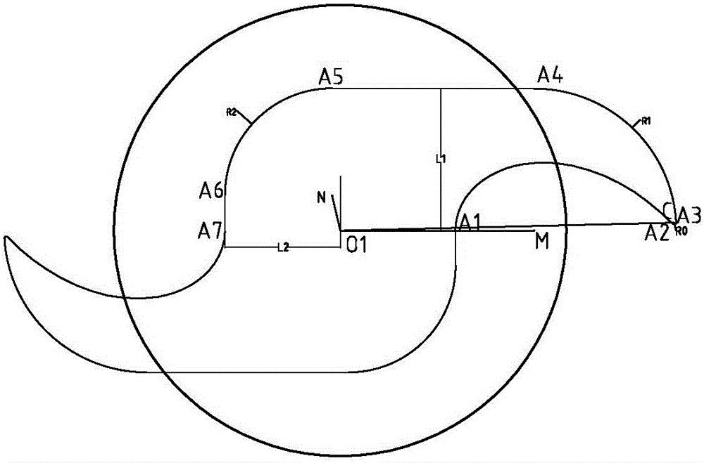
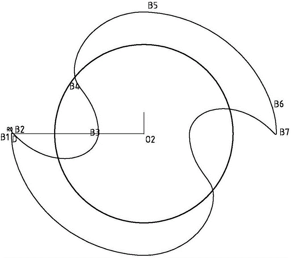
[0056] like Figure 1-Figure 4 As shown, the profile of the special claw rotor in the present invention is characterized in that it includes a special claw rotor A and a special claw rotor B that are meshed, and both the special claw rotor A and the special claw rotor B are centrally symmetrical structure; the special claw rotor A described by the arc R 0 Curve conjugate curve A1A2, arc one A2A3, arc two A3A4, straight line A4A5, arc three A5A6 and straight line two A6A7 six-segment lines; the special claw rotor B is composed of arc R 0 Curve B1B2, arc-conjugate curve B2B3, arc-two-conjugate curve B3B4, straight-line-conjugate curve B4B5, arc-three-conjugate curve B5B6 and straight-line two-conjugate curve B6B7 six-segment line.

[0057] The arc R 0 Curve conjugate curve A1A2 is centered on the center point of the special claw rotor A, and the arc R of the sp...


PUM


Abstract

The invention relates to a special claw type rotor profile, and belongs to the technical field of claw type vacuum pumps.The special claw type rotor profile comprises a special claw type rotor A and a special claw type rotor B which are meshed with each other and are both of a central symmetry structure; the special claw type rotor A is composed of an arc R0 curve conjugate curve A1A2, a first arc A2A3, a second arc A3A4, a first straight line A4A5, a third arc A5A6 and a second straight line A6A7, and the special claw type rotor B is composed of an arc R0 curve B1B2, a first arc conjugate curve B2B3, a second arc conjugate curve B3B4, a first straight line conjugate curve B4B5, a third arc conjugate curve B5B6 and a straight line conjugate curve B6B7.Compared with an existing single-claw rotor, on the premise that the exradius Rm is equal to the pitch radius R of the rotor, the coefficient of utilization of capacity of a pump is greatly improved by 30-50%, high pumping speed can be realized, and the special claw type rotor profile is high in practicability.

Description

Technical field [0001] The invention relates to a special claw rotor profile and belongs to the technical field of claw vacuum pumps. Background technique [0002] Claw vacuum pump (including claw vacuum pump, claw compressor and claw expander, etc.) is a new type of positive displacement fluid pressurized conveying machinery. It consists of two special claw-type rotors as well as a pump body, end cover, sealing device, etc. When the claw vacuum pump works, the two rotors perform synchronous rotational motion in opposite directions to compress or expand the pump body, thereby achieving the purpose of pressurized fluid transportation. Existing claw vacuum pumps mostly use a single claw profile, which results in a low volume utilization coefficient of the pump, a low pumping speed, and poor practical performance. Contents of the invention [0003] Based on the above deficiencies in the prior art, the problem to be solved by the present invention is to provide a pump with a...

Claims


Application Information

Patent Timeline
IPC IPC(8): F04C18/14F04C29/00
CPCF04C18/084F04C18/14
Inventor 张东庆雷春栋陈宗武徐元蕾辛玲玲
Owner 伯仲(山东)工业设备有限公司
Learn More