

Self-water-diversion type water-containing plate and duct-type air conditioner
A water tray and tray bottom technology, applied in heating methods, prevention of condensed water, space heating and ventilation, etc., can solve potential safety hazards, condensation on the bottom of the air duct machine, affecting product safety, etc., to improve safety sexual effect
- Summary
- Abstract
- Description
- Claims
- Application Information
AI Technical Summary
Problems solved by technology
Method used
Image

Examples
Embodiment 1
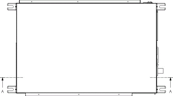
[0035] refer to Figure 5 As shown, this embodiment is a self-guided water receiving tray 10 installed inside the indoor unit of the air duct machine. The water receiving tray 10 is a rectangular structure with an upper opening as a whole. Sidewalls 12, 13 and two long sidewalls 14, 15, the tops of all sidewalls are provided with flanging, and a drain outlet 16 is provided near the middle part of the outer bottom of one of the short sidewalls 12 . The bottom 11 of the water tray 10 and all side walls are integrally formed, and the whole is made of EPS foam material.
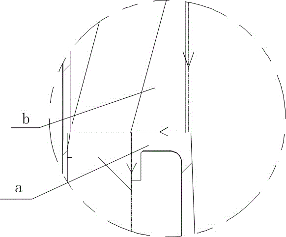
[0036] Such as Figure 6 , 7 As shown, wherein, the top of the short side wall 12 is provided with an outer flange 17, and the top surface of the outer flange 17 is provided with a flange 18. Correspondingly, the top of the short side wall 13 is provided with the same flange structure.
Embodiment 2
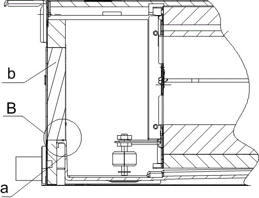
[0038] Such as Figure 4 , 6, 7, this embodiment is an indoor unit of an air duct machine, the indoor unit includes a housing 20, the housing 20 includes a front side panel 21, a rear side panel (not shown in the figure), and a left side panel 22 , the right side plate 23, the top plate 24, the evaporator 30 is installed in the housing 20, the self-guided water receiving tray 10 of the embodiment 1 is installed at the bottom of the evaporator 30, specifically the short side wall 12 of the water receiving tray 10 is connected to the shell The right side plate 23 of the body 20 is installed in cooperation, the short side wall 13 is installed in cooperation with the left side plate 22 of the housing 20 , and the drain port 16 passes through the right side plate 23 .
[0039] The inside of the housing 20 is installed next to the right side plate 23 is the thermal insulation part 40, the top of the side wall of the water receiving tray 10 cooperates with the thermal insulation par...
PUM
 Abstract
Description
Claims
Application Information