High-power white-light LED light source based on transparent ceramic fluorescent tube

A technology of LED light source and transparent ceramics, applied in electrical components, electrical solid devices, circuits, etc., can solve the problems of uneven light intensity distribution, development and application limitations, poor light uniformity, etc., achieve uniform light emission, improve light efficiency, cost low effect

Inactive Publication Date: 2016-07-13
XUZHOU NORMAL UNIVERSITY
View PDF9 Cites 2 Cited by
  • Summary
  • Abstract
  • Description
  • Claims
  • Application Information

AI Technical Summary

Problems solved by technology

This technology coats the phosphor powder on the lampshade to avoid direct contact between the phosphor powder and the blue light chip, but this technology also has disadvantages such as astigmatism loss, uneven light intensity distribution, and poor light uniformity.
Therefore, the power of the current white LED light source is generally small, even if there is a high-power LED light source, the price is high, and the development and application are limited.

Method used


Image

  • High-power white-light LED light source based on transparent ceramic fluorescent tube
  • High-power white-light LED light source based on transparent ceramic fluorescent tube

Examples


Embodiment 1

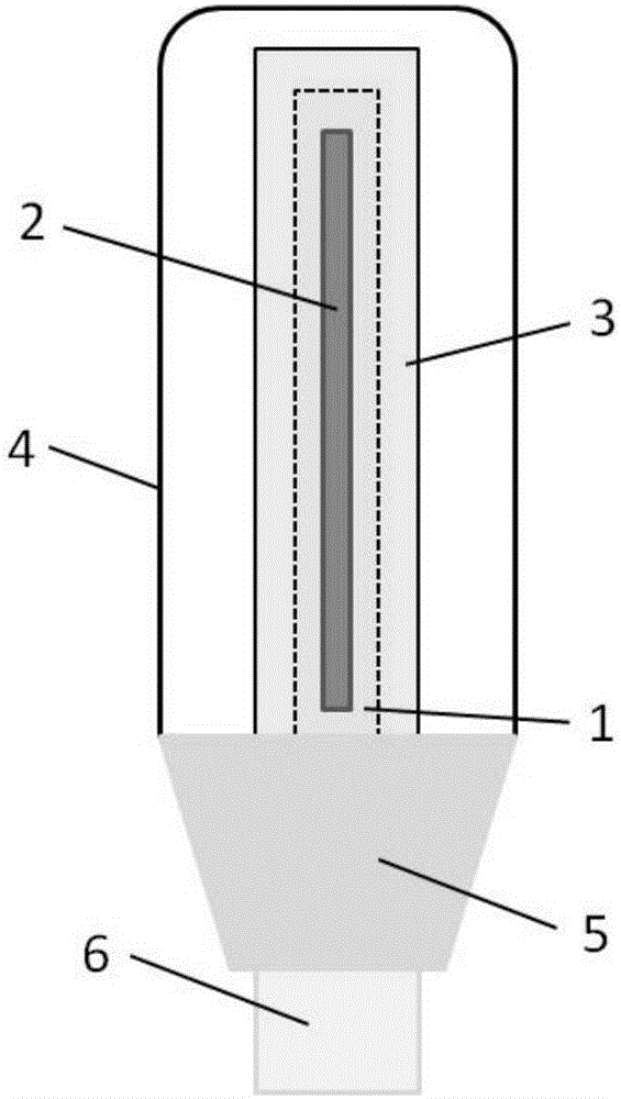
[0026] (1) Prepare mutually suitable metal heat-conducting columns 1, blue light chips 2, transparent ceramic fluorescent tubes 3, high light-transmitting packaging shells (polypropylene) 4, heat sinks 5 and electrodes 6;

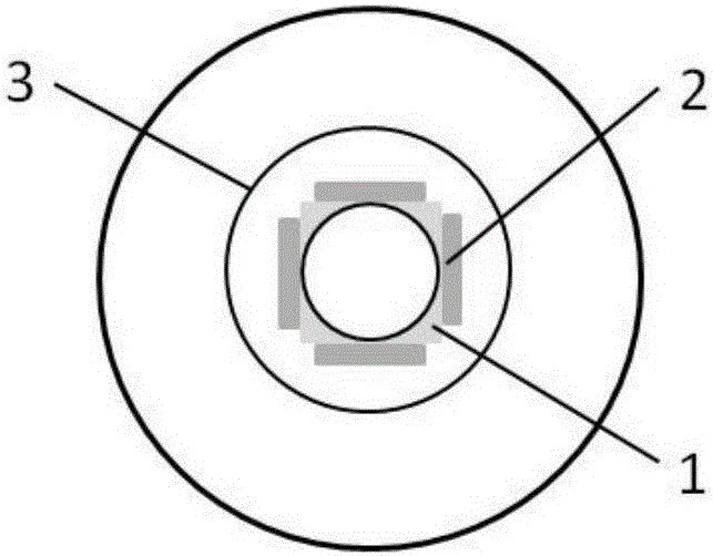
[0027] (2) Arrange the COB blue-ray chips 2 with a thickness of 2mm in a linear and vertical manner at an interval of 3mm, and paste them on the rectangular metal heat conduction column 1 with a bottom side length of 15mm and a height of 100mm through silica gel. 1 70% of the surface area;

[0028] (3) A tubular Ce:YAG transparent ceramic fluorescent tube 3 is arranged outside the regular rectangular parallelepiped metal heat conduction column 1 with the COB blue light chip 2, and its transmittance at 550nm is 70%, and its density is 99.7%. Keep a distance of 20mm between them;

[0029] (4) The transparent ceramic tube 3 and the metal heat conduction column 1 are placed on the upper surface of the heat sink 5, and the commercially available screw electrode...

Embodiment 2

[0034] (1) Prepare mutually suitable metal heat-conducting columns 1, blue light chips 2, transparent ceramic fluorescent tubes 3, high light-transmitting packaging shells (polypropylene) 4, heat sinks 5 and electrodes 6;

[0035] (2) Arrange the blue LED lamp beads 2 with a thickness of 4mm linearly and vertically at an interval of 4mm, and paste them on the metal heat-conducting column 1 with a regular triangular prism shape with a bottom side length of 10mm and a height of 200mm through silica gel. 80% of the surface area of ​​column 1;

[0036] (3) A hollow Ce:YAG transparent ceramic fluorescent tube 3 is set outside the regular triangular prism-shaped metal heat-conducting column 1 pasted with blue LED lamp beads 2, and its transmittance at 550nm is 75%, and its density is 99.0%. Keep a distance of 40mm between the two;

[0037] (4) The transparent ceramic tube 3 and the metal heat conduction column 1 are placed on the upper surface of the heat sink 5, and the commercial...

Embodiment 3

[0041] (1) Prepare mutually suitable metal heat-conducting columns 1, blue light chips 2, transparent ceramic fluorescent tubes 3, high light-transmitting packaging shells (polypropylene) 4, heat sinks 5 and electrodes 6;

[0042] (2) Arrange the COB Blu-ray chips 2 with a thickness of 2mm in a linear and vertical manner at an interval of 4mm, and paste them on the metal heat-conducting column 1 with a bottom side length of 15mm and a height of 40mm on the metal heat-conducting column 1 with a thickness of 2mm. 1 50% of the surface area;

[0043](3) A hollow Ce:YAG transparent ceramic fluorescent tube 3 is set outside the regular triangular prism-shaped metal heat-conducting column 1 with the COB blue-ray chip 2 attached, and its transmittance at 550nm is 72%, and its density is 99.3%. Keep a distance of 10mm between them;

[0044] (4) The transparent ceramic tube 3 and the metal heat conduction column 1 are placed on the upper surface of the heat sink 5, and the commercially...


PUM

PropertyMeasurementUnit
diameteraaaaaaaaaa
heightaaaaaaaaaa
heightaaaaaaaaaa

Abstract

The invention relates to a high-power white-light LED light source based on a transparent ceramic fluorescent tube, and the LED light source consists of a metal thermal conducting column (1), a blue light chip (2), the transparent ceramic fluorescent tube (3), a high-transmittance packaging housing (4), a cooling fin (5), and an electrode (6). The blue light chip (2) is pasted on the metal thermal conducting column (1), and the transparent ceramic fluorescent tube (3) is disposed outside the metal thermal conducting column (1). The transparent ceramic fluorescent tube (3) and the metal thermal conducting column (1) are disposed at the center of the upper end face of the cooling fin (5). The high-transmittance packaging housing (4) is reversely buckled on the upper end face of the cooling fin (5), and a heat dissipation material is disposed in the high-transmittance packaging housing (4). The electrode (6) is located exactly below the cooling fin (5), and is connected with the cooling fin (5) through a connecting line, and the other end of the electrode (6) is connected with an external power supply. The light source employs the technology of remote excitation, employs the transparent ceramic fluorescent tube (3) to replace fluorescent powder, and enables the transparent ceramic fluorescent tube (3) to be separated from the blue light chip (2). The prepared LED light source is good in light uniformity, is easier for heat dissipation, and can be used as a large-power LED light source.

Description

technical field [0001] The present invention relates to a high-power white LED light source based on remote excitation technology, in particular to a high-power white LED light source based on a transparent ceramic fluorescent tube, which uses a transparent ceramic fluorescent tube to replace the fluorescent powder directly coated on the blue chip , the technical idea of ​​separating it from the Blu-ray chip. Background technique [0002] White light LED light sources have gradually replaced incandescent lamps and fluorescent lamps, and are widely used in people's daily life. At present, there are two main ways of emitting light from white LED light sources. The white light LED light source widely circulated in the market mainly uses monochromatic light and phosphor powder to excite to form white light. Compared with incandescent lamps and fluorescent lamps, white LED light sources have a longer service life, stronger safety and reliability, and are more environmentally fr...

Claims


Application Information

Patent Timeline
Patent Type & Authority Applications(China)
IPC IPC(8): H01L25/075H01L33/50
CPCH01L25/0753H01L33/505
Inventor 陈浩贲玥张乐陈旭陈德军
Owner XUZHOU NORMAL UNIVERSITY
Why Eureka
Try Eureka