Movable multi-rotor unmanned aerial vehicle autonomous base station system

A technology of a multi-rotor unmanned aerial vehicle and a base station system, which is applied in the field of the autonomous base station system of a movable multi-rotor unmanned aerial vehicle, can solve the problem that it is difficult to meet the application requirements, unfavorable to the development of the autonomous flight capability of the unmanned aerial vehicle, and the wireless transmission bandwidth is low. and other problems, to achieve the effect of reducing the integration complexity and the cost of airborne hardware resources, facilitating continuous and autonomous operations, and reducing human input.

Active Publication Date: 2016-07-13
INST OF AUTOMATION CHINESE ACAD OF SCI
View PDF11 Cites 50 Cited by
  • Summary
  • Abstract
  • Description
  • Claims
  • Application Information

AI Technical Summary

Problems solved by technology

[0003] However, the existing multi-rotor UAVs are generally insufficient in autonomy, and it is difficult to meet the above requirements
For example, most drones use a "one-to-one" working method, that is, one operator corresponds to one aircraft and operates by remote control. This mode of operation not only greatly increases labor costs, but also is not conducive to unmanned The development of autonomous flight capabilities
Another example is that one of the biggest bottlenecks of multi-rotors at this stage is their insufficient battery life. The flight time of most drones does not exceed 40 minutes, which seriously limits the application of continuous long-term operations.
For another example, in complex flight missions, large-scale data transmission between the UAV and the ground monitoring center is required, but based on the existing data transmission / image transmission radio technology, its wireless transmission bandwidth is low, and it is difficult to meet the application requirements

Method used


Image

  • Movable multi-rotor unmanned aerial vehicle autonomous base station system
  • Movable multi-rotor unmanned aerial vehicle autonomous base station system
  • Movable multi-rotor unmanned aerial vehicle autonomous base station system

Examples


Embodiment Construction

[0052] The technical problems solved by the embodiments of the present invention, the technical solutions adopted and the technical effects achieved are clearly and completely described below in conjunction with the accompanying drawings and specific embodiments. Apparently, the described embodiments are only some of the embodiments of the present application, not all of them. Based on the embodiments in the present application, all other equivalent or obviously modified embodiments obtained by persons of ordinary skill in the art without creative efforts fall within the protection scope of the present invention. Embodiments of the invention can be embodied in many different ways as defined and covered by the claims.

[0053] It should be noted that, in the following description, many specific details are given for the convenience of understanding. It may be evident, however, that the present invention may be practiced without these specific details.

[0054] It should be no...


PUM


Abstract

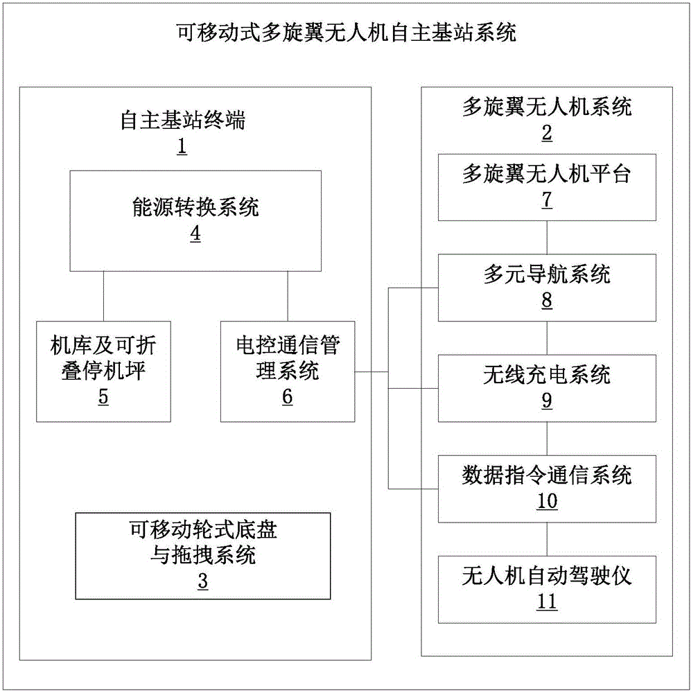
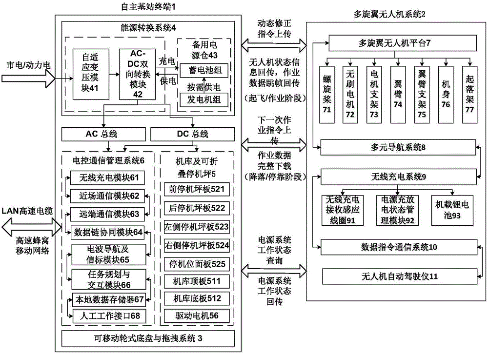
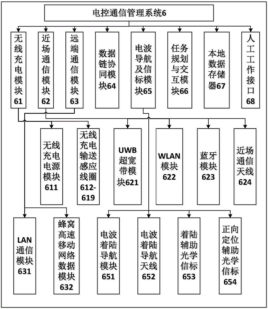
The invention discloses a movable multi-rotor unmanned aerial vehicle autonomous base station system.The system comprises an autonomous base station terminal (1) and a multi-rotor unmanned aerial vehicle system (2), wherein the autonomous base station terminal (1) comprises a movable wheel undercarriage and traction system (3), an energy conversion system (4), a hangar and foldable parking apron (5) and an electric control communication management system (6), and the multi-rotor unmanned aerial vehicle system (2) comprises a multi-rotor unmanned aerial vehicle platform (7), a multisource navigation system (8), a wireless charging system (9), a data command communication system (10) and an unmanned aerial vehicle autopilot (11).By the adoption of the system, the technical problems of providing wireless charging, task planning, cluster strategy allocation, airborne audio / video data exchange and storage for a multi-rotor unmanned aerial vehicle are solved, and the autonomous collaborative work capacity, cruising ability and data transmission capacity with a ground system of multiple multi-rotor unmanned aerial vehicles are improved.

Description

technical field [0001] Embodiments of the present invention relate to the technical field of continuous autonomous operation of unmanned aerial vehicles, and in particular to a mobile autonomous base station system for multi-rotor unmanned aerial vehicles. Background technique [0002] In recent years, multi-rotor drones have been more and more widely used due to their simple flight mechanism, excellent operational performance, increasingly mature flight control technology, and lower prices than fixed-wing and helicopters. In addition to consumer fields such as aerial photography, multi-rotor UAVs have increasingly strong application requirements in special fields such as agricultural plant protection, ecological protection, border monitoring, police security, and disaster rescue. The increasingly complex application environment has put forward more and more stringent performance requirements for multi-rotor UAVs, such as multi-UAV cooperative operations, continuous long-ter...

Claims


Application Information

Patent Timeline
Patent Type & Authority Applications(China)
IPC IPC(8): H04B5/00H04B7/185H04W88/08
CPCH04B5/00H04B7/18517H04B7/18528H04W88/08
Inventor 蒲志强高俊龙易建强谭湘敏
Owner INST OF AUTOMATION CHINESE ACAD OF SCI
Why Eureka
Try Eureka