Heat dissipation structure, manufacturing method therefor, and device employing heat dissipation structure

A technology of heat dissipation structure and manufacturing method, which is applied in the direction of cooling/ventilation/heating transformation, electrical components, electric solid devices, etc., and can solve the problems of affecting the computing efficiency of electronic equipment, high manufacturing cost, and poor heat dissipation effect

Inactive Publication Date: 2016-07-13
QI DING TECHNOLOGY QINHUANGDAO CO LTD +1
View PDF4 Cites 4 Cited by
  • Summary
  • Abstract
  • Description
  • Claims
  • Application Information

AI Technical Summary

Problems solved by technology

With the rapid development of LED technology, the calorific value and heat flux density of LEDs are relatively high. However, according to relevant analysis, the lower the temperature of LEDs, the more energy-saving they are. The higher the temperature, the shorter the life of the lamps. 1 ℃, its luminous intensity will be reduced by about 1%
For electronic equipment using high-end chips, high temperature will affect the computing efficiency of electronic equipment and consume more energy
At present, there are two types of heat dissipation methods for LEDs and chips: active heat dissipation and passive heat dissipation: active heat dissipation, such as adding a cooling mechanism and other external heat dissipation devices, has faster heat dissipation efficiency, but requires a larger area and has a relatively fixed shape. High manufacturing cost; passive heat dissipation, such as using metal heat transfer to naturally dissipate heat, has defects such as slow heat dissipation speed and poor heat dissipation effect

Method used


Image

  • Heat dissipation structure, manufacturing method therefor, and device employing heat dissipation structure
  • Heat dissipation structure, manufacturing method therefor, and device employing heat dissipation structure
  • Heat dissipation structure, manufacturing method therefor, and device employing heat dissipation structure

Examples


Embodiment Construction

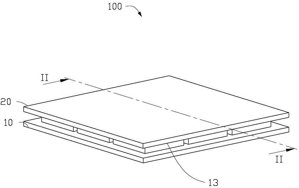
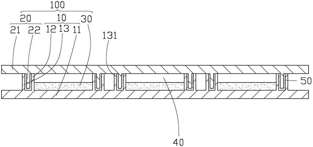
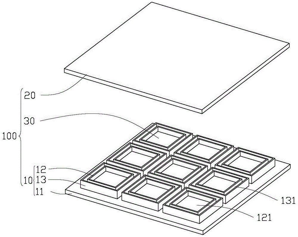
[0033] see Figure 1~2 , a preferred embodiment of the present invention provides a heat dissipation structure 100, which is used for heat-generating components (such as microprocessors, memory modules, cache memory, etc.) memory chips, etc.) for heat dissipation. The heat dissipation structure 100 includes a base 10 and a cover 20 covering the base 10 . At least one airtight cavity 40 is formed between the cover body 20 and the base 10 , and each airtight cavity 40 is filled with a radiator 30 .

[0034] Both the base 10 and the cover 20 are made of heat-conducting materials. The heat conducting material can be metal, and the metal is preferably copper.

[0035] The radiator 30 does not completely fill the airtight cavity 40 , and the radiator 30 is made of phase change material (PCM-PhaseChangMaterial). When the cooling body 30 absorbs heat to increase its temperature to the phase transition temperature, the cooling body 30 undergoes a phase change and further absorbs an...


PUM


Abstract

The invention discloses a heat dissipation structure, and the structure comprises a pedestal and a cover body covering the pedestal. At least one closed cavity is formed between the pedestal and the cover body, and the pedestal and the cover body are made of thermal conduction materials. The pedestal comprises a bottom plate, at least one annular convex part disposed on the bottom plate in a convex manner, and second annular convex parts which respectively surrounds the corresponding first annular convex part. The central area of each first annular convex part is provided with a first storage groove, and each first annular convex part and the corresponding second annular convex part form a clamping groove therebetween. The interior of each clamping groove is provided with adhesive. The cover body comprises a top plate and at least one third annular convex part disposed at the top plate in a convex manner. The cover body covers the pedestal, and each third annular convex part is embedded in the clamping groove through the adhesive to form a closed cavity, wherein the interior of the closed cavity is provided with a heat dissipation body. The structure can enable the heat dissipation body to be sealed in the closed cavity better. Moreover, the invention also relates to a manufacturing method for the structure, and a device employing the structure.

Description

technical field [0001] The invention relates to a heat dissipation structure, a manufacturing method thereof, and a device using the heat dissipation structure. Background technique [0002] In recent years, LED lamps and various electronic devices have been widely used. With the rapid development of LED technology, the calorific value and heat flux density of LEDs are relatively high. However, according to relevant analysis, the lower the temperature of LEDs, the more energy-saving they are. The higher the temperature, the shorter the life of the lamps. At 1°C, the luminous intensity will decrease by about 1%. For electronic equipment using high-end chips, high temperature will affect the computing efficiency of the electronic equipment and consume more energy. At present, there are two types of heat dissipation methods for LEDs and chips: active heat dissipation and passive heat dissipation: active heat dissipation, such as adding a cooling mechanism and other external h...

Claims


Application Information

Patent Timeline
IPC IPC(8): H05K7/20H01L23/427
Inventor 黄昱程
Owner QI DING TECHNOLOGY QINHUANGDAO CO LTD
Why Eureka
Try Eureka