
Coated tool

A tool and coating technology, which is applied in the manufacture of tools, drilling accessories, sputtering coating, etc., can solve the problems of poor wear resistance

Active Publication Date: 2016-07-13
TUNGALOY CORP
View PDF9 Cites 4 Cited by
  • Summary
  • Abstract
  • Description
  • Claims
  • Application Information

AI Technical Summary

Problems solved by technology

Therefore, the coated tool disclosed in Patent Document 2 has a problem of poor wear resistance.

Method used


Image

  • Coated tool
  • Coated tool
  • Coated tool

Examples


Embodiment 1

[0105] As a base material, a P20 cemented carbide corresponding to ISO standard SEKN1203AGTN tool shape was prepared. The base materials of Invention Products 1 to 10 and Comparative Product 9 were subjected to dry shot blasting under the conditions shown in Table 1.

[0106]

[0107] Next, a metal evaporation source having the composition of the coating layer shown in Table 3 was placed in the reaction vessel of the arc ion plating apparatus. Fix the prepared substrate on the fixed metal part of the turntable inside the reaction vessel.

[0108] After that, evacuate to make the pressure in the reaction vessel reach 5.0×10 -3 Vacuum below Pa. After evacuation, heating was carried out in a heater in the reaction vessel until the temperature of the substrate reached 500°C. After heating, Ar gas was introduced into the reaction container so that the pressure in the reaction container reached 5.0 Pa. Next, ion bombardment treatment was performed on the substrate under the c...

Embodiment 2

[0152] As a base material, a cermet in the shape of an ISO standard SEKN1203AGTN tool was prepared. The substrates of Invention Products 11 and 12 and Comparative Product 11 were subjected to dry shot blasting under the conditions shown in Table 8.

[0153]

[0154] Next, a metal evaporation source having the composition of the coating layer shown in Table 10 was placed in the reaction vessel of the arc ion plating apparatus. Fix the prepared substrate on the fixed metal part of the turntable inside the reaction vessel.

[0155] After that, evacuate to make the pressure in the reaction vessel reach 5.0×10 -3 Vacuum below Pa. After evacuation, heating was carried out in a heater in the reaction vessel until the temperature of the substrate reached 500°C. After heating, Ar gas was introduced into the reaction container so that the pressure in the reaction container reached 5.0 Pa. Next, ion bombardment treatment was performed on the substrate under the conditions shown in...


PUM

PropertyMeasurementUnit
particle diameteraaaaaaaaaa
thicknessaaaaaaaaaa

Abstract

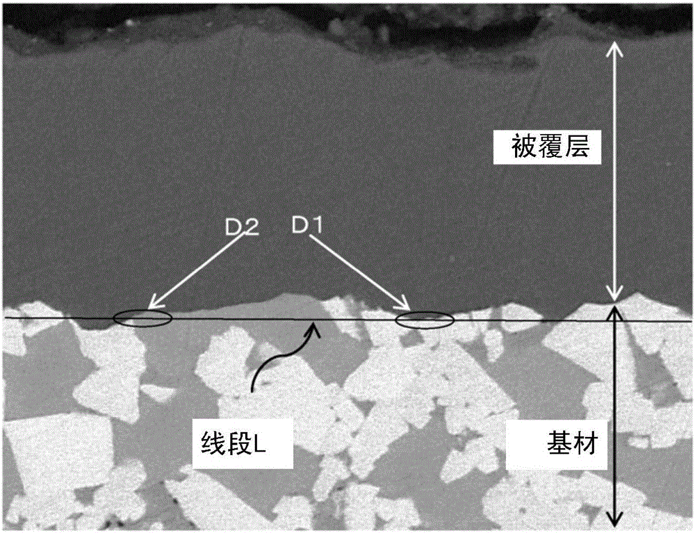
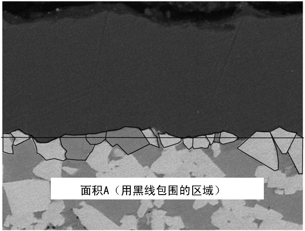
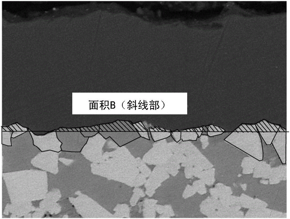
Provided is a coated tool which is wear-resistant and damage resistant, and which has a long service life. This coated tool comprises a base material and a coating layer. The base material comprises a plurality of hard particles and a bonding phase that bonds the plurality of hard particles. The coating layer contains a compound layer. The ratio B / A determined by procedures (1) to (6) is at least 0.2 but less than 0.5. (1) A cross section perpendicular to the surface of the base material is extracted along a reference length (S) in a direction parallel to the surface of the base material. (2) In the cross section thus extracted, the total area (A) of the cross section of hard particles that touch the coating layer is determined. (3) At the interface between the coating layer and the base material, of the plurality of interface parts that are formed between adjoining hard particles, the first interface part (D1) which is at the deepest position, and the second interface part (D2) which is at the second deepest position, are determined. (4) A line (L) is drawn to pass through D1 and D2. (5) In the cross section of the hard particles which touch the coating layer, the total area (B) of the cross section that is on the coating layer side of the line (L) is determined. (6) The value for B / A is calculated.

Description

technical field [0001] The present invention relates to coated tools. Background technique [0002] Coated tools are widely used in the cutting of steel, cast iron, stainless steel, heat-resistant alloys, etc. For example, coated tools in which a TiN layer or a TiAlN layer is formed on the surface of a substrate such as cemented carbide, cermet, or cBN sintered body are widely used. [0003] A covered tool described in Patent Document 1 is known as a prior art of covered tools. The coated tool described in Patent Document 1 includes a substrate containing hard particles and a binder phase, and a coating. Concavities and convexities are formed on the surface of the hard particles in contact with the coating. The roughness Rz of the inclined surface of the substrate is 1.0 μm or more and 30 μm or less. [0004] In addition, a coated tool described in Patent Document 2 is also known as a prior art of a covered tool. The coated tool described in Patent Document 2 includes a...

Claims


Application Information

Patent Timeline
Patent Type & Authority Applications(China)
IPC IPC(8): B23B27/14B23B51/00B23C5/16C23C14/06
CPCC23C14/0664C23C30/005
Inventor 城地司
Owner TUNGALOY CORP
Learn More