

Preheating method and circuit of X-ray tube lamp filament of CT equipment
A technology for X-ray tubes and preheating circuits, applied in X-ray equipment, electrical components, radiation generation arrangements, etc., can solve problems such as high filament temperature, difficulty in quickly reaching the target value of tube current value, single preheating current, etc.
- Summary
- Abstract
- Description
- Claims
- Application Information
AI Technical Summary
Problems solved by technology
Method used
Image

Examples
no. 1 example
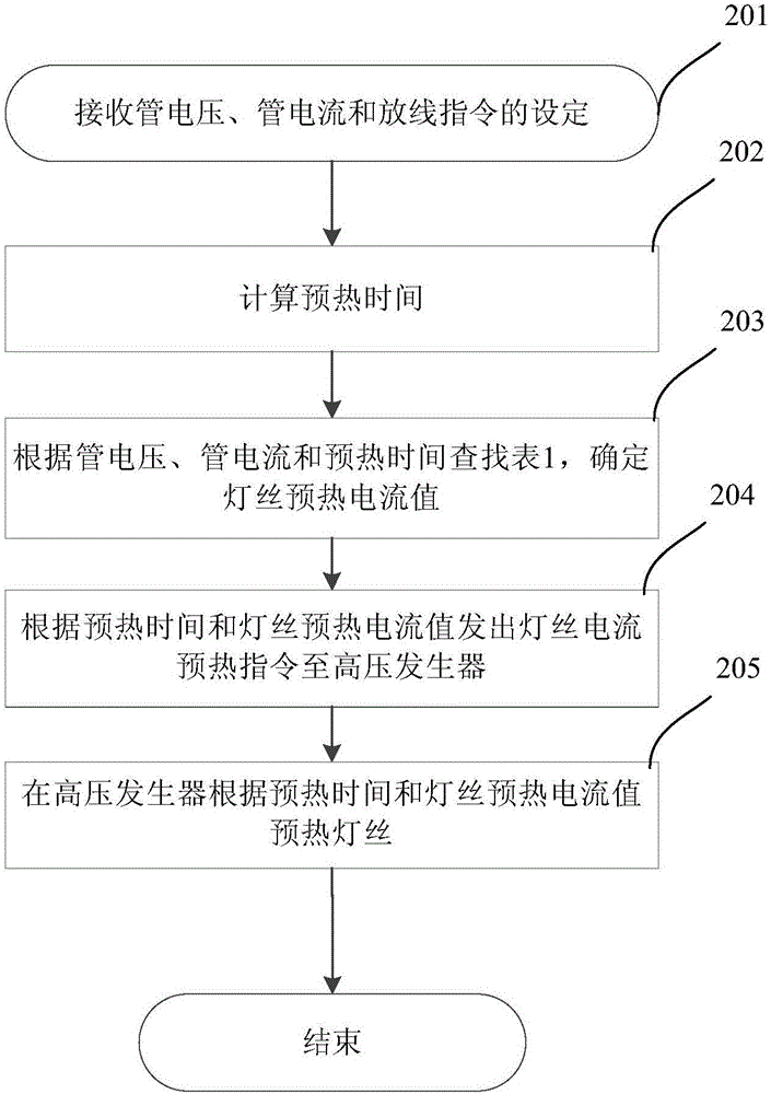
[0034] In a typical scanning scenario, the filament warm-up time is around the standard warm-up time. Usually, the warm-up time is equal to the standard warm-up time. In a few cases, the warm-up time is less than the standard warm-up time. Of course, there is also a situation where the warm-up time is higher than the standard warm-up time. For this purpose, a lookup table for the normal scanning scene is prepared in advance as shown in Table 1.
[0035] Tube Filament Heating Table 1
[0036]
[0037] As shown in Table 1, the tube voltage is fixed at 80kV, and the tube current is between 10-120mA or even higher. Filament warm-up time t preheatAmong them, t1 is the standard preheating time, the left column is below the standard preheating time (preheat0 =3.3732, reduced to the second preheating current value F of the preheating time [t1, t2) preheat1 =3.3232, and then decrease to the third preheating current value F when the preheating time ≥ t2 preheat2 = 3.2589.
[00...
no. 2 example
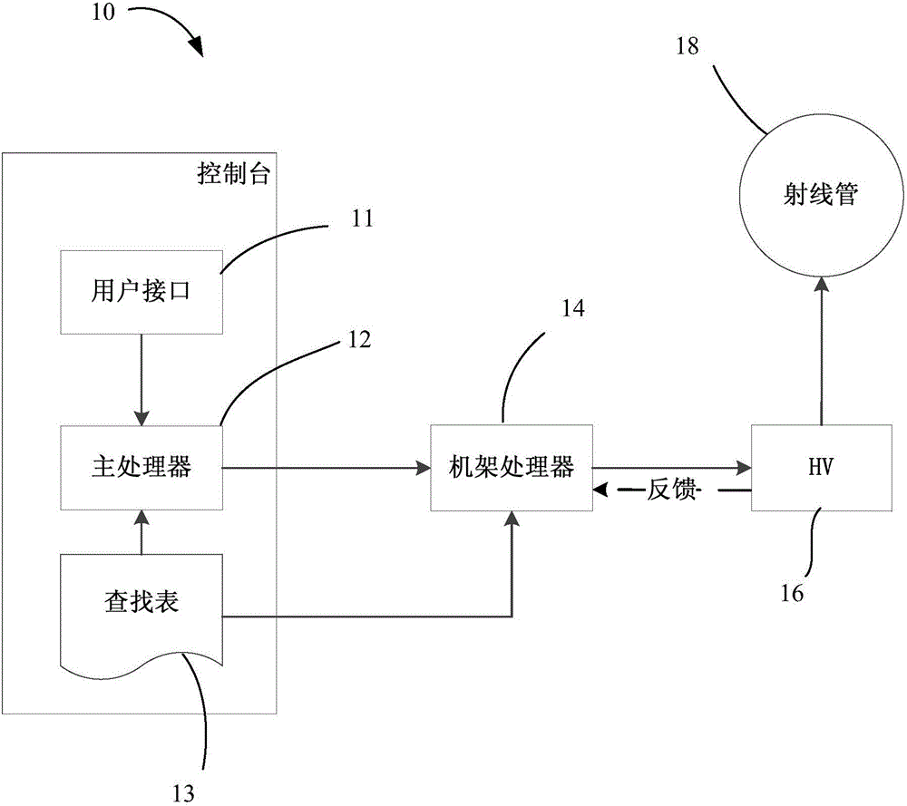
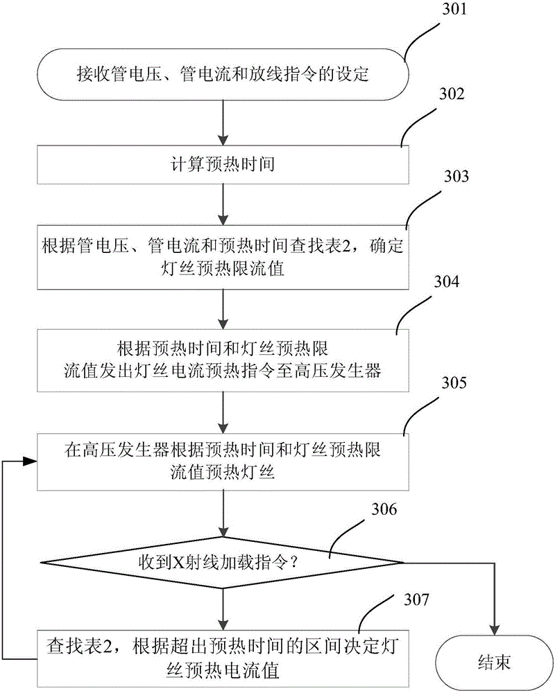
[0050] In conventional scanning scenarios, it is more common for the warm-up time available to be extended during the warm-up process than for the initially determined warm-up time to be higher than the standard warm-up time. For example, after the circuit is preheated according to the initially determined preheating time, the main processor 12 may not have received the X-ray loading instruction, and the wire payoff has not yet started. In order to ensure that the filament temperature does not exceed the target value due to the longer heating time, the filament preheating is controlled by changing the filament preheating current value in time intervals to obtain good mA performance.
[0051] To this end, the bulb filament heating table 2 is established through testing, as follows:
[0052] Tube Filament Heating Table 2
[0053]
[0054] Referring to Table 2, t1 is the standard warm-up time, Δt1 is the short warm-up time after t1, Δt2 is the small warm-up time after Δt1, an...
no. 3 example
[0065] In another scanning scenario, the time interval between the current and the next two wire-releasing times may be short, and the next wire-releasing will start before the temperature of the filament drops to the initial value. In this case, using a fixed filament preheating current will result in poor mA value stability. Therefore in this case, the main processor 12 also refers to the initial filament temperature value to determine the filament preheating current value.
[0066] The following table 3 is the heat dissipation table of the bulb filament.
[0067] Tube Filament Heat Dissipation Table 3
[0068]
[0069] In Table 3, different time intervals are set: 0~t1, t1~t2, t2~t3 and >t3. For a specific kV and mA, when the time interval between the last payout and the current payout is different In the time interval of , the corresponding initial temperature is obtained.
[0070] Table 4 below is the bulb filament heating table. This table determines the preheating...
PUM
 Abstract
Description
Claims
Application Information