
Degreasing device for degreasing tank

A technology of degreasing tank and oil inlet channel, which is applied in the direction of grease/oily substance/floating matter removal device, water pollutants, liquid separation, etc. It can solve the problems of production quality that cannot be ignored, large liquid level fluctuations, low oil content, etc. problem, to achieve the effect of increasing the extraction effect, no loss of things, and small relaxation time

Active Publication Date: 2017-10-27
AUTOMOTIVE ENG CORP +1
View PDF7 Cites 0 Cited by
  • Summary
  • Abstract
  • Description
  • Claims
  • Application Information

AI Technical Summary

Problems solved by technology

[0002] The pre-treatment of automobile painting is an important process line, and degreasing is the primary key process. In order to obtain good coating quality and meet the requirements of coating corrosion resistance and appearance decoration, the degreasing liquid in the degreasing tank is used for a period of time Finally, there will be a lot of oil slicks or oil particles, and the oil content is only about several thousand ppm, but its impact on production quality cannot be ignored. This requires oil-water separation of the degreasing liquid. Traditional oil-water separation generally uses pumps Suction the surface liquid layer or set up a branch in the circulation pipeline to obtain the liquid and separate it from oil and water. However, because the liquid level in the degreasing tank fluctuates greatly, the liquid sucked by the pump or the grease content in the circulation pipeline is very low, resulting in actual The effective oil removal rate is low, resulting in energy waste

Method used


Image

  • Degreasing device for degreasing tank
  • Degreasing device for degreasing tank
  • Degreasing device for degreasing tank

Examples


Embodiment Construction

[0024] The present invention will be described in further detail below in conjunction with the accompanying drawings and specific embodiments. It should be understood that the specific embodiments described here are only used to explain the present invention, not to limit the present invention.

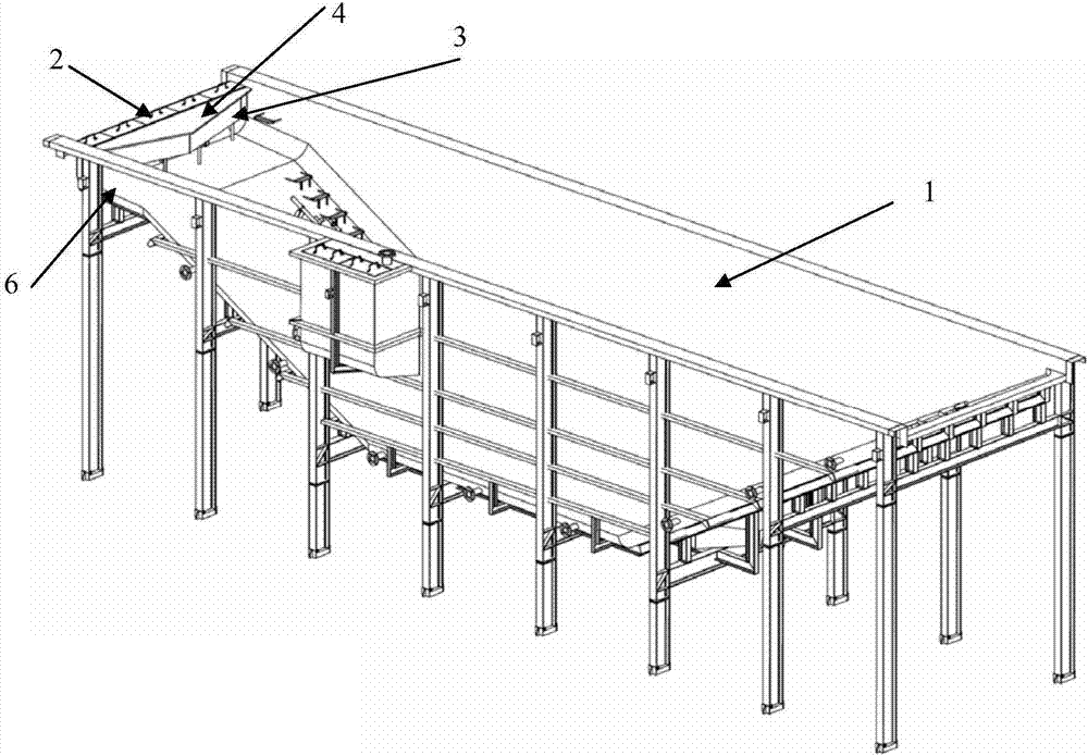
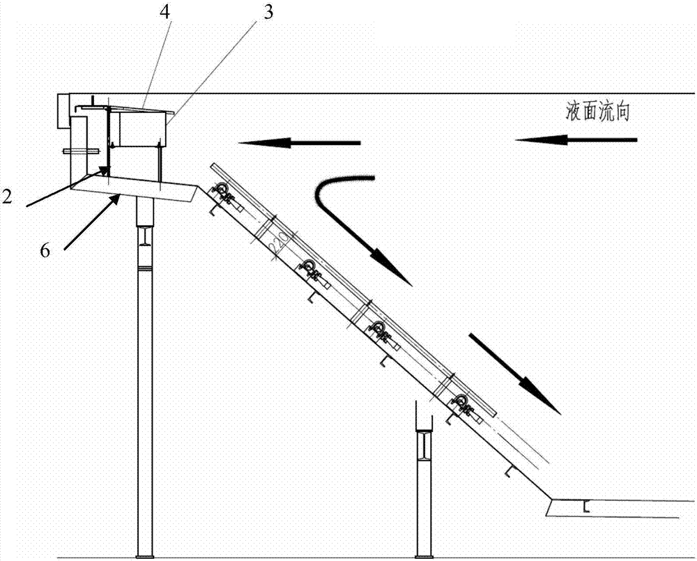
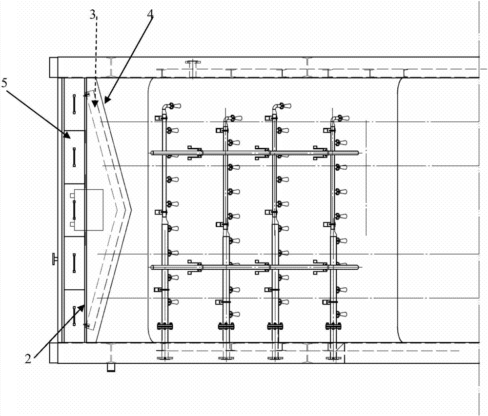
[0025] Such as Figure 1-3 As shown, the front part of the left end plate of the degreasing tank 1 of the present invention is provided with a longitudinal partition 2 to form an isolation area where liquid cannot directly enter relative to the space of the degreasing tank on the right side. Shaped or corner-shaped splitter plate 3 protruding to the right, the upper part of the splitter plate is higher than the predetermined height of the liquid level, generally 4-8cm higher than the liquid level, and the front and rear ends of the splitter plate are kept in contact with the side wall of the degreasing tank. The oil passage, the longitudinal partition and the oil inlet passage are pr...


PUM


Abstract

The invention discloses a degreasing unit of a degreasing tank. The left end of the degreasing tank protrudes leftwards to form an extension section, a longitudinal partition is arranged in the front of the extension portion so as to form an isolation area, a splitter plate with the middle protruding rightwards is arranged on the right side of the longitudinal partition, the upper portion of the splitter plate is higher than the set liquid level, grease inlet passages are reserved between the front and rear ends of the splitter plate and the side wall of the degreasing tank, slots are formed in the positions, corresponding to the grease inlet passages, of the longitudinal partition, and an unpowered deflection-type oil skimmer is arranged in the isolation area. Fluctuation of surge is eliminated at the liquid inlet end with relatively small wave through the isolation area and by the aid of the splitter plate, meanwhile the liquid containing more grease on the upper layer is collected, oil liquid collection effect of the oil skimmer is improved effectively, and overall degreasing effect is improved.

Description

technical field [0001] The invention relates to the technical field of automobile processing, in particular to a degreasing device for a degreasing tank. Background technique [0002] The pre-treatment of automobile painting is an important process line, and degreasing is the primary key process. In order to obtain good coating quality and meet the requirements of coating corrosion resistance and appearance decoration, the degreasing liquid in the degreasing tank is used for a period of time In the end, there will be a lot of oil slick or oil particles, and the oil content is only about thousands of ppm, but its impact on production quality cannot be ignored, which requires oil-water separation of the degreasing liquid. Traditional oil-water separation generally uses pumps Suction the surface liquid layer or set up a branch in the circulation pipeline to obtain the liquid and separate it from oil and water. However, due to the large fluctuation of the liquid level in the deg...

Claims


Application Information

Patent Timeline
Patent Type & Authority Patents(China)
IPC IPC(8): B01D17/032C02F1/40C02F101/32
CPCB01D17/0214C02F1/40C02F2101/32
Inventor 王海军林茂武尚华斌
Owner AUTOMOTIVE ENG CORP
Learn More