Boring cutter installing shaft, boring assembly and boring mill

A technology for installing shafts and boring tools, which is applied in boring/drilling, accessories of toolholders, drilling/drilling equipment, etc. Meet the requirements, poor rigidity and other problems, to achieve the effects of not being easy to bend and deform, increasing the outer diameter, and improving the molding quality

Inactive Publication Date: 2016-07-20
赵圣和
View PDF7 Cites 2 Cited by
  • Summary
  • Abstract
  • Description
  • Claims
  • Application Information

AI Technical Summary

Problems solved by technology

Due to the long length of the tapered double barrel, when the boring tool extends into the hole to be processed to process the tapered shaped hole, the length of the boring bar cantilevered into the hole to be processed is relatively large, and the rigidity is poor. One end is often bent and deformed under the action of cutting force, resulting in the inner peripheral surface of the processed tapered hole not meeting the requirements for use, and the taper of the tapered hole cannot meet the requirements.

Method used


Image

  • Boring cutter installing shaft, boring assembly and boring mill
  • Boring cutter installing shaft, boring assembly and boring mill
  • Boring cutter installing shaft, boring assembly and boring mill

Examples


Embodiment Construction

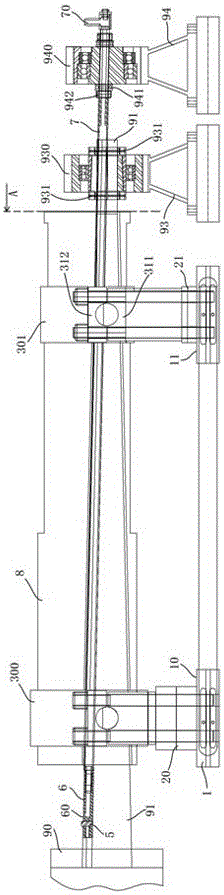
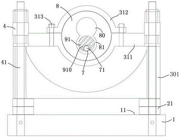
[0022] The embodiment of boring machine of the present invention: mainly be used in processing cone double barrel, as figure 1 , 3 As shown, it includes a frame on which a workpiece mounting frame for installing workpieces to be processed is arranged. The workpiece mounting frame includes a base 1. The base 1 is used for fixed connection with the machine tool slide plate and can move forward and backward with the machine tool slide plate. The base 1 is respectively provided with a front support surface 10 and a rear support surface 11. The workpiece mount also includes a front mounting seat 300 corresponding to the front support surface 10 and a rear mounting seat 301 corresponding to the rear support surface 11. The front mounting seat 300 is used to fix the large diameter section of the front end of the workpiece, and the rear mounting seat 301 is used to fix the workpiece. The small diameter section of the rear end of machine barrel workpiece 8.

[0023] The workpiece mou...


PUM


Abstract

The invention provides a boring cutter installing shaft, a boring assembly and a boring mill. The boring mill comprises a rack and the boring assembly. The boring assembly comprises a boring cutter rotating relative to a workpiece, and the boring cutter installing shaft. The boring cutter installing shaft comprises a shaft body, the shaft body is used for stretching into a to-be-machined hole of the workpiece during using, and the two ends of the shaft body extend out of the two ends of the to-be-machined hole to form two supporting ends. A guiding structure used for guiding moving assembly of the boring cutter so as to enable the boring cutter to machine the to-be-machined hole into a needed forming hole is arranged on the shaft body in the length direction in an extending manner. The boring mill further comprises a driving mechanism used for driving the boring cutter to move along the guiding structure in a guiding manner. When the boring assembly is used for conducting boring, due to the fact that the two ends of the shaft body are the supporting ends and are stably supported, the whole boring cutter installing shaft is good in stability and not prone to bending or deforming, the boring cutter moves along the shaft body in the guiding manner and rotates relative to the workpiece, the boring cutter is stable and reliable when boring the inner circumferential face of the to-be-machined hole, vibration cannot happen, the inner hole machining precision is greatly improved, and the machining quality is guaranteed.

Description

technical field [0001] The invention relates to a boring tool installation shaft, a boring assembly and a boring machine. Background technique [0002] The barrel of the conical twin-screw plastic extruder is referred to as the cone twin barrel, which includes a barrel extending front and back. The outer diameter of the front end of the barrel is large, and the outer diameter of the rear end is small. Two intersecting tapered holes for mounting tapered screws. When the two tapered holes in the cone double barrel are processed, two holes to be processed are generally processed on the cylindrical blank first, and then the holes to be processed are processed into tapered shaped holes by a boring tool. Due to the long length of the tapered double barrel, when the boring tool extends into the hole to be processed to process the tapered shaped hole, the length of the boring bar cantilevered into the hole to be processed is relatively large, and the rigidity is poor. One end ofte...

Claims


Application Information

Patent Timeline
Patent Type & Authority Applications(China)
IPC IPC(8): B23B41/06B23B27/10B23B29/04
CPCB23B27/10B23B29/04B23B41/06
Inventor 赵圣和
Owner 赵圣和
Why Eureka
Try Eureka