Lamp holder assembly equipment

A technology for assembling equipment and lamp caps, which is applied in the direction of assembly machines, metal processing equipment, manufacturing tools, etc., can solve the problems of high labor cost and low assembly efficiency, and achieve the effects of low cost, simple structure and high efficiency

Inactive Publication Date: 2016-07-20
SHENZHEN XUANSHUO INTELLIGENT MANUFACTURING TECHNOLOGY CO LTD
View PDF7 Cites 21 Cited by
  • Summary
  • Abstract
  • Description
  • Claims
  • Application Information

AI Technical Summary

Problems solved by technology

[0002] In the prior art, when assembling the lamp holder, it is usually assembled manually, which re

Method used


Image

  • Lamp holder assembly equipment
  • Lamp holder assembly equipment
  • Lamp holder assembly equipment

Examples


Example Embodiment

[0033] The embodiments of the present invention are described in detail below with reference to the accompanying drawings, but the present invention can be implemented in many different ways as defined and covered by the claims.

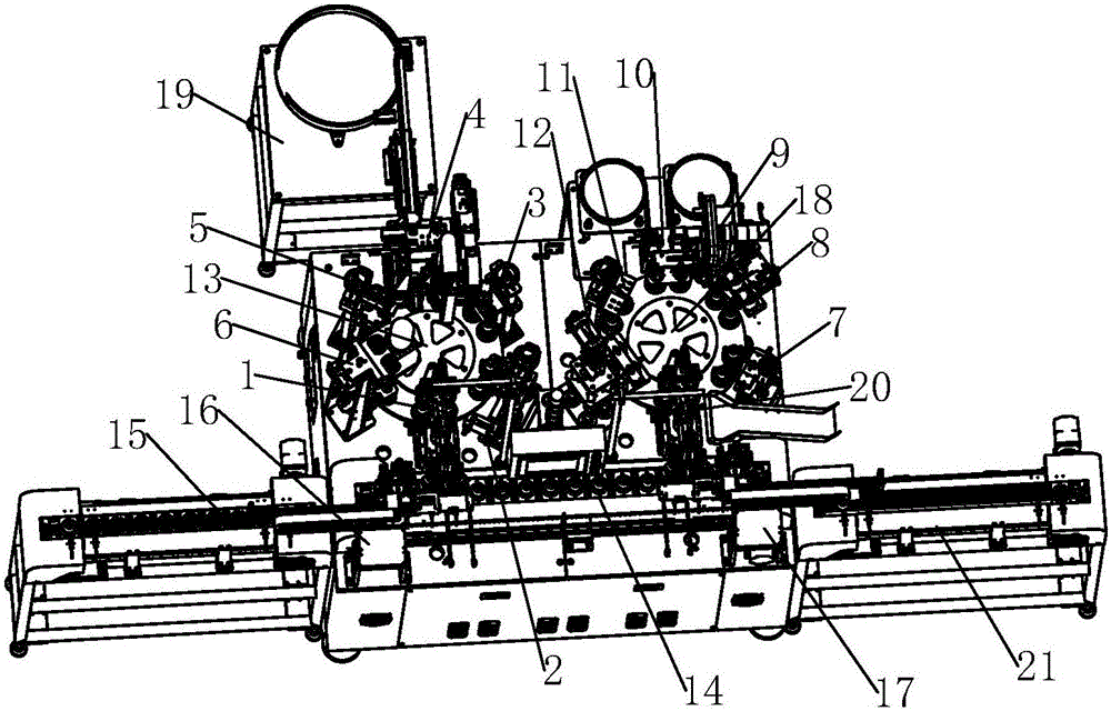
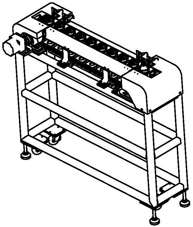
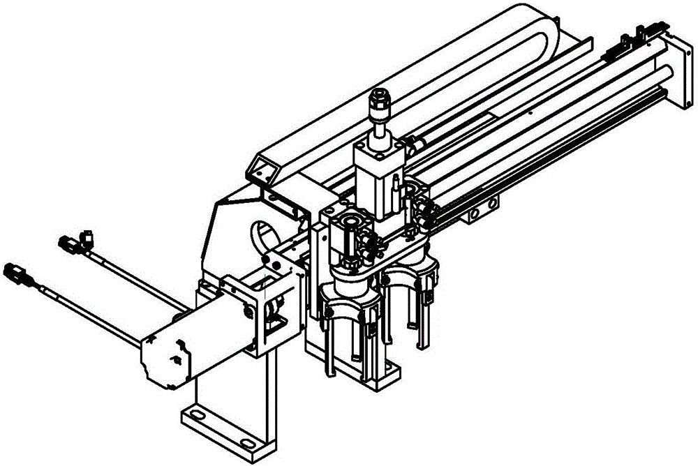
[0034] Please refer to Figure 1-Figure 17 , The present invention provides a lamp head assembly equipment, including: a first connecting conveyor chain mechanism 15; a feeding manipulator 16 for grabbing and moving the workpiece on the first connecting conveyor chain mechanism 15 to the conveyor chain transmission mechanism 14 The first rotary feeding mechanism 1 is used to move the workpiece from the conveyor chain transmission mechanism 14 to the first turntable mechanism 13, and the rotation path of the first turntable mechanism 13 is sequentially provided with a live wire correction mechanism for processing the workpiece. 2. Lamp holder calibration mechanism 3, screw fitting mechanism 4, screw pressing mechanism 5 and screw tightening mechanism ...


PUM


Abstract

Lamp holder assembly equipment comprises a feeding manipulator, a first rotary feeding mechanism and a second rotary feeding mechanism. The feeding manipulator is used for grasping and moving a workpiece which is arranged on a first connection conveying chain mechanism onto a conveying chain transmission mechanism. The first rotary feeding mechanism is used for moving the workpiece onto a first rotary table mechanism from the conveying chain transmission mechanism. A live line correcting mechanism, a lamp holder correcting mechanism, a screw base assembly mechanism, a screw base pressing and correcting mechanism and a screw base screwing mechanism which are used for processing the workpiece are arranged on the rotary path of the first rotary table mechanism in order. The first rotary feeding mechanism moves the workpiece which is subjected to the processing of the screw base screwing mechanism to the conveying chain transmission mechanism. The second rotary feeding mechanism is used for moving the workpiece which is arranged on the conveying chain transmission mechanism and is subjected to the processing of the screw base screwing mechanism to a second rotary table mechanism. A lightening testing mechanism, a live line cutting mechanism, a rivet feeding mechanism, a rivet pressing mechanism and a screw base riveting mechanism are arranged on the rotary path of the second rotary table mechanism. The lamp holder assembly equipment has the characteristics of being simple in structure, low in cost and high in efficiency.

Description

technical field [0001] The invention relates to the field of lamp cap assembly, in particular to a lamp cap assembly device. Background technique [0002] In the prior art, when assembling the lamp cap, it is usually assembled manually, which requires a lot of manpower, which not only has high labor cost, but also has low assembly efficiency. Contents of the invention [0003] The invention provides a lamp cap assembling device with simple structure, low cost and automatic lamp cap assembly. [0004] In order to solve the above problems, as an aspect of the present invention, a lamp cap assembly equipment is provided, including: a first connecting conveying chain mechanism; a feeding manipulator, used to grasp the workpiece on the first connecting conveying chain mechanism Take and move to the conveyor chain transmission mechanism; the first rotary feeding mechanism is used to move the workpiece from the conveyor chain transmission mechanism to the first turntable mechani...

Claims


Application Information

Patent Timeline
IPC IPC(8): B23P21/00
CPCB23P21/00
Inventor 刘忠军余金金谢维坤张佳欲薛伟杰赵玉涛
Owner SHENZHEN XUANSHUO INTELLIGENT MANUFACTURING TECHNOLOGY CO LTD
Why Eureka
Try Eureka