A steel bar binding machine based on a driven opening and closing clamp device

A strapping machine and clamping block technology, applied in packaging, strapping materials, strapping machine parts, etc., can solve the problems of complex opening and closing conduit structure, complex control action, and many parts mechanisms, so as to save control procedures, The effect of simplifying the motion mechanism and avoiding failure

Active Publication Date: 2018-05-11
天津市福鼎机电设备有限公司
View PDF5 Cites 12 Cited by
  • Summary
  • Abstract
  • Description
  • Claims
  • Application Information

AI Technical Summary

Problems solved by technology

[0004] The above-mentioned opening and closing catheter is composed of a top-tightening hydraulic cylinder, a four-bar linkage mechanism and a guide tube. During the entire working process, the opening and closing catheter needs to be actively opened and closed (when threading the wire, the opening and closing catheter is closed to play a guiding role in threading. ; when the mechanical claw pulls the steel wire, the opening and closing conduit is opened and the steel wire is released), the opening and closing action needs to be driven by the hydraulic cylinder through the control program, so that on the one hand, the structure of the opening and closing conduit is more complicated, there are more parts and mechanisms, and the cost is higher ; On the other hand, the opening and closing of the catheter requires a program to drive the hydraulic cylinder, and the hydraulic cylinder passes through a four-bar linkage, which makes its control action complicated and prone to failure

Method used


Image

  • A steel bar binding machine based on a driven opening and closing clamp device
  • A steel bar binding machine based on a driven opening and closing clamp device
  • A steel bar binding machine based on a driven opening and closing clamp device

Examples


Embodiment Construction

[0034] The technical solutions of the present invention will be further described below in conjunction with specific embodiments.

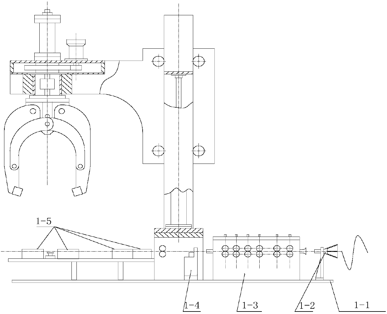
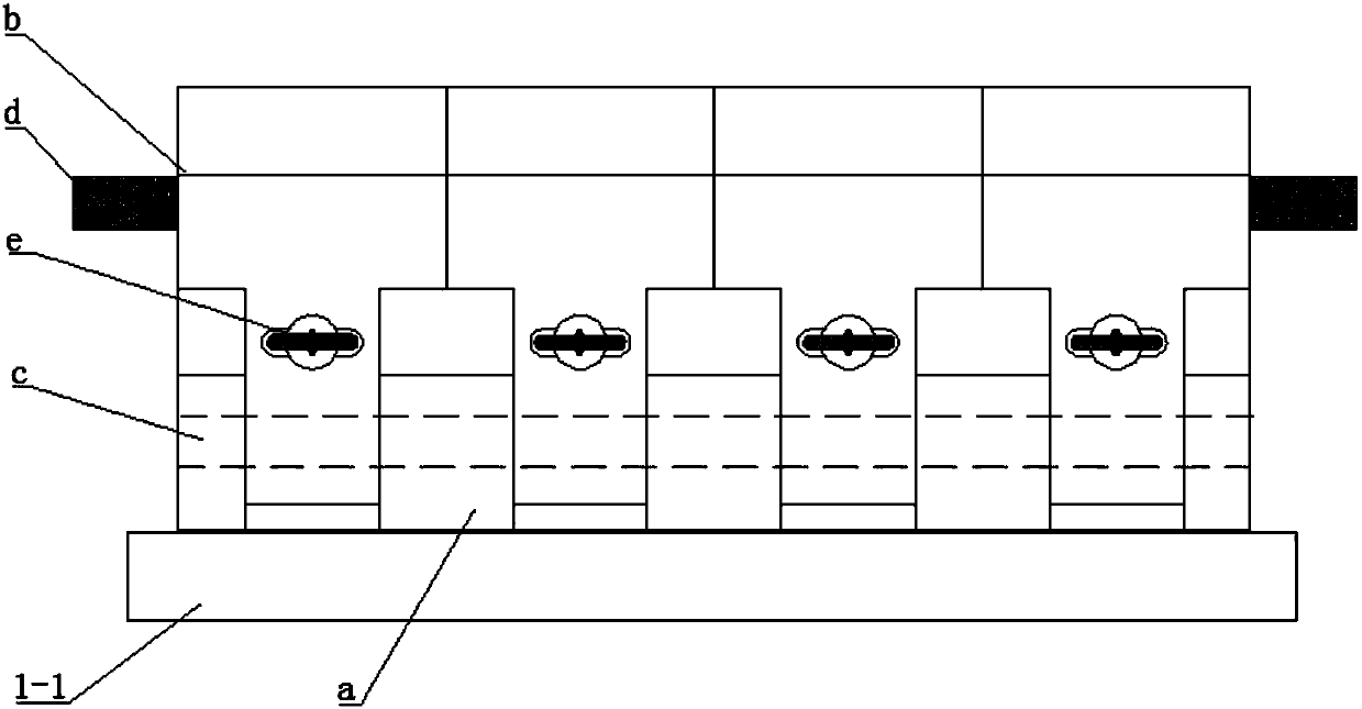
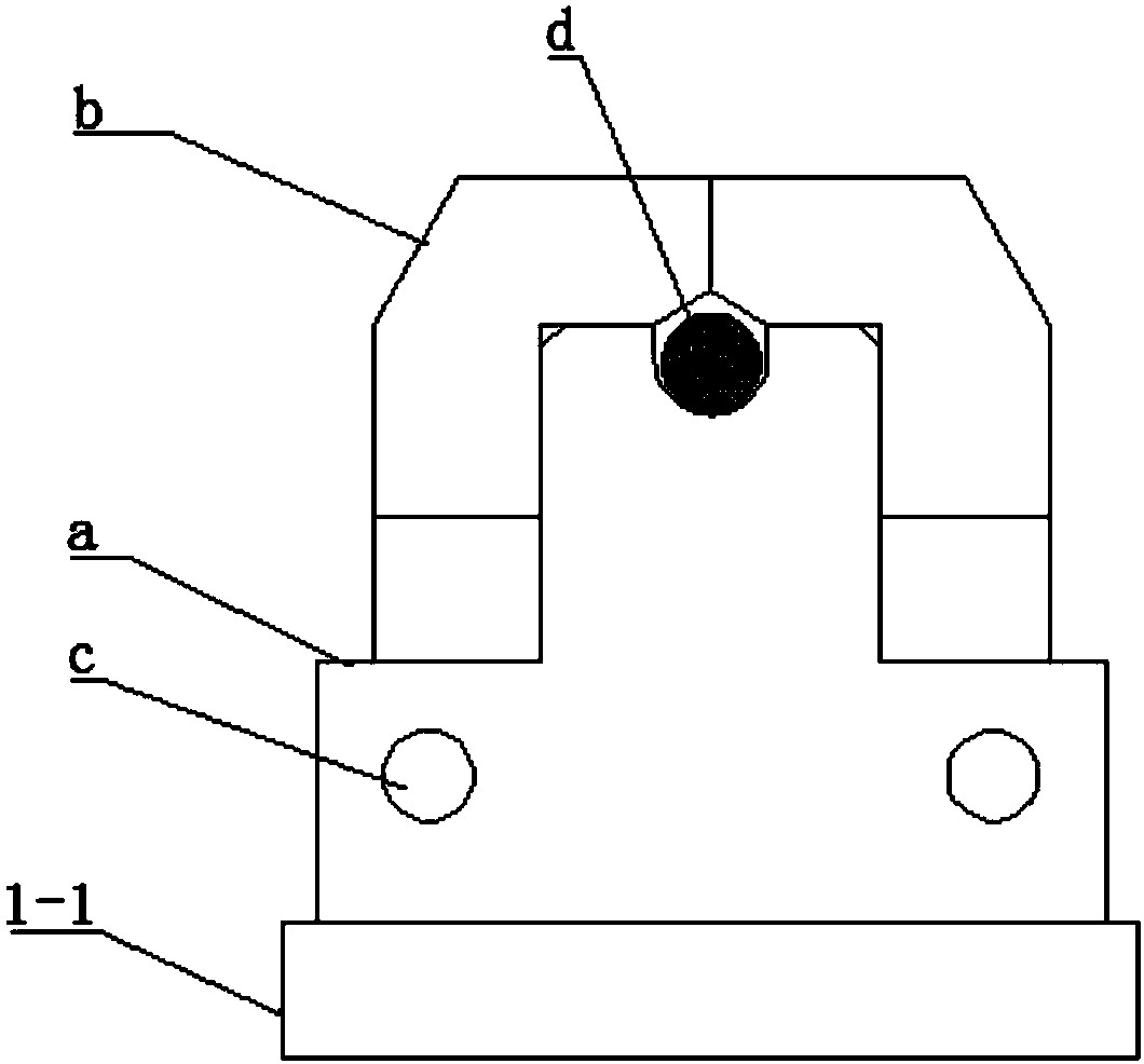
[0035] A steel bar binding machine based on a driven opening and closing clamp device, see the attached figure 1 , which includes a bottom threading straightening workbench and a rotary clamping mechanical claw. The bottom threading straightening workbench consists of a base 1-1, a random wire frame 1-2, a roller straightening machine 1-3, and a hydraulic shear 1- 4. The driven opening and closing clamping device 1-5 is composed of a column, and the random wire frame, roller leveler, hydraulic shear, and driven opening and closing clamping device are fixed on the base in sequence from right to left. The column is vertically fixed on the base; the rotary clamping mechanical claw is arranged on the column so that it can move up and down through the bracket. The overall structure of the steel bar binding machine based on the driven opening and closi...


PUM


Abstract

The invention discloses a steel bar bundling machine based on a driven opening and closing clamp device, wherein the driven opening and closing clamp device is used to replace the opening and closing in the "automatic manipulator steel bar bundling machine" with publication number 104925293A Conduit, the driven opening and closing clamping block device includes a base and claws, the top of the base is a boss, and the top surface of the boss is provided with a groove for penetrating the bundled steel wire, which is symmetrical on both sides of the boss of the base There are a plurality of bases arranged at equal intervals along the length of the boss, the bottom ends of the claws are hinged between two adjacent bases, and the claws are connected by springs passing through the bosses, and the springs are claws The clamping and closing force is provided between the claws. When the claws are clamped and closed, the claw heads of the claws are closed and docked, so that a threading channel is formed between the lower wall of the claw head of the claws and the groove on the base boss. When the steel wire is pulled up, the steel wire in the wire passage will push upward on the lower wall of the claw head, prompting the claw to open on both sides with the pin shaft as the rotation axis, thereby pulling the steel wire out of the wire passage .

Description

technical field [0001] The invention belongs to the technical field of automatic mechanical equipment, and in particular relates to a steel bar bundling machine based on a driven opening and closing clamping block device. Background technique [0002] In traditional industries, the packaging and bundling of steel bars is often done by manual use of simple tools. Usually, workers traverse the steel wires from the bottom of the steel bundles, then cut the required length of steel wires, and finally use wrenches, pliers Or a special tool such as a manipulator pulls up the steel wire, rotates and tightens it to bundle the steel tendons. In the case of manual labor, due to the high work intensity, it is easy to cause employee fatigue, and there is a high possibility of work-related injuries, which is not conducive to safe production. At the same time, it also makes the bundling efficiency low and the bundling quality is not high. Therefore, an automated steel bar bundling equipme...

Claims


Application Information

Patent Timeline
Patent Type & Authority Patents(China)
IPC IPC(8): B65B13/06B65B13/18B65B13/28B65B27/10
CPCB65B13/06B65B13/18B65B13/28B65B27/10
Inventor 白礼彬孙关起刘永福
Owner 天津市福鼎机电设备有限公司
Why Eureka
Try Eureka